

Abstract
The development of unmanned aerial vehicles (UAVs) and their integration into our daily life have rapidly accelerated in recent years. Despite these advancements, the production of UAVs often requires specialized and costly equipment. However, with the rapid evolution of additive manufacturing (AM) technologies, it is now possible to design lightweight, optimized structures that can be manufactured easily and quickly. This approach enables faster design iterations, reduces the need for multiple parts and material usage during production, and significantly minimizes waste. A hybrid UAV combines the advantages of vertical take-off and landing (VTOL) capabilities with the efficient cruising performance of a fixed-wing aircraft. This study investigates the feasibility of using AM for the manufacturing of a 3.8-meter wingspan hybrid UAV. The system consists of two components: a hybrid aircraft and a parachute drone carried by the hybrid aircraft. Following the mechanical and aerodynamic design of the air vehicle, it was fabricated using a rapid prototyping approach that integrates AM and composite production techniques. This study demonstrates that even large-scale UAVs can be produced with AM-supported design and manufacturing. This method supports on-demand customization, reduces material waste, and promotes innovation and sustainability in UAV production. It is anticipated that this approach can make UAV production more accessible to the general public, potentially accelerating the development of UAV technology.
Keywords
- Additive Manufacturing
- Hybrid UAV
- Parcel Delivery UAV
- Vacuum Infusion Method
1. Introduction
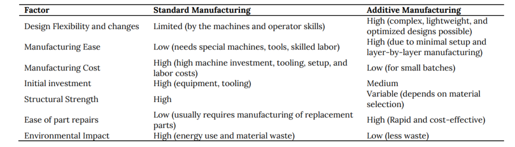
Unmanned aerial vehicles (UAVs) (also called drones) are autonomous or remote-controlled aerial vehicles ranging from small enough to fit in the palm of your hand (21 cm) to a wingspan of 42 meters. Although the word drone is used instead of UAV, it is preferred to refer to smaller, consumer-class models weighing 2 kg and below. UAV or Unmanned Aircraft System (UAS) is preferred for professional aircraft. In recent years, along with the developments (Mohsan et al., 2023; Telli et al., 2023; Çetinsoy et al., 2012; Hissa and Mothé, 2018), we have witnessed their useful applications in the fields of defense (Chaturvedi et al., 2019), agriculture (Radoglou-Grammatikis et al., 2020; Srivastava et al., 2023), health (De Silvestri et al., 2023; Boutilier et al., 2017; Ackerman and Strickland, 2018), logistics (Li et al., 2022; Koetsier, 2021; DHL), transportation (Rajendran and Srinivas, 2020; Smirnov et al., 2023; Kellermann et al., 2020), and search and rescue (Lyu et al., 2023; Martinez-Alpiste et al., 2021). Although UAV technology has progressed, manufacturing requires specialized equipment and intricate procedures. The rise of rapid prototyping, driven by 3D printers (Shahrubudin et al., 2019), has made custom production of various items more accessible to everyone. As the 3D printing techniques emerged, using these technologies for UAV manufacturing was inevitable. The approach has the potential to reduce weight, manufacturing costs, and deployment time (Moon et al., 2014; Ferro et al., 2016). For a mini drone, designing and printing a drone model with a 3D printer is common. Various studies share their findings (Esakki et al., 2019; Klippstein et al., 2018; Goh et al., 2017). According to the literature, the first printed plane was the Southampton University Laser Sintered Aircraft (SULSA) in 2011 (Marks, 2011). Small drones and UAVs were manufactured using 3D printers (Banfield, 2013; McKinnon, 2016). British Royal Navy successfully launched a 3D-printed UAV for maritime patrol missions in 2016 (3D printing industry, 2016). (Aktas et al., 2016) presents the iterative design process of the TURAC, a VTOL UAV. It emphasizes a low-cost prototyping methodology. A master’s thesis discusses the role of rapid prototyping in developing a novel amphibious UAV (Zlatan, 2021). There are various demonstrations and failures with printed propellers. (Biswas et al., 2018) reveals that the 3D-printed propeller experiences higher stress levels throughout its structure compared to the non-3D-printed propeller, making it more susceptible to breaking. On the other hand, (Alves et al., 2021) propose solutions to overcome failures and compare wind tunnel tests to numerical predictions for validation. Recent studies propose a quieter Toroidal Propeller designed with computational fluid dynamics (CFD), and manufactured with 3D printing techniques as an alternative (Jansen, 2024). A patent by (Sebastian and Strem, 2017), with (MIT, 2023) proposes a significant reduction of discernible noise. Weight reduction is one of the critical goals of aerial system design. One can use internal lattice structures and numerical topology optimization to reduce the weight of UAVs. (Yap et al., 2023) argues that topology optimization combined with 3D printing offers a safe and reliable approach to micro-UAV design and prototyping. Isotropic materials exhibit the same physical properties (e.g., strength) in all directions. However, 3D printing procedures and some materials used can lead to anisotropy in many 3D printed objects. Therefore, it is necessary to validate the material’s strength through destructive or non-destructive testing. The wings and control surfaces of an aircraft are vital components that require a balance between strength and weight. This can make their manufacturing challenging and costly. Combining 3D printing and composite manufacturing offers a promising approach to making aircraft components more affordable and efficient. Wings and other control surfaces can be manufactured using the Vacuum Infusion Process (VIP), a technique that leverages vacuum pressure to impregnate resin into a laminate (Baker, 2004). Table 1 compares standard versus additive manufacturing techniques across various factors. This study explores the feasibility of manufacturing a 3.8-meter hybrid UAV with the fused deposition modeling (FDM) technique and the use of VIP. An FDM 3D printer was used to create the aircraft body, various parts, and molds for VIP. Wings and control surfaces were built via VIP. The study involves aircraft design, manufacturing techniques, and assembly procedures.
Table 1. The comparison of standard versus additive manufacturing techniques
This paper is organized as follows. In Section 2, aerodynamic and mechanical design to develop a UAV for a particular task has been explained. Manufacturing techniques, post-processing operations, and assembly of the aircraft are explained in detail in Section 3. Final remarks on cost and delivery time benefits were presented in Section 4. Conclusions and future work are given in Section 5.
2. Design of the Aircraft
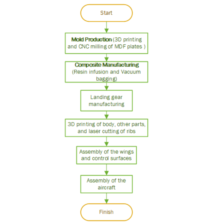
UAV design and manufacturing process involves various steps as outlined in Figure 1. The process starts with Concept & Design phase where the main design will be created. Once the design is ready, the prototype development phase will follow, which usually involves building a small-scale version of the aircraft for concept, visual, or wind tunnel testing. Once the design proves to be acceptable the team can proceed to Manufacturing & Assembly phase. All the materials for manufacturing, propulsion, control, and electronical parts will be purchased. The wings, body, and control surfaces of the aircraft will be manufactured. Electronic cards may be designed. Quality of the manufactured parts should be checked before proceeding to the assembly step, where the frame, body, propulsion system, electronic parts such as sensors, and battery will be assembled. This step may also require software installation for controllers, telemetry systems, and ground station (if any). Once the aircraft is complete Testing & Validation phase will start. The team will perform functional testing of each subsystem, flight testing, as well as any other tests required by regulations. If there are any problems, the team may need to update, redesign, or re-manufacture certain parts to overcome the problem. If the testing phase is completed successfully and there is a market for the aircraft, the team may proceed to the Production & Deployment phase, in which the system will be redesigned and updated for mass production, following additional tests and quality control inspections, and delivery to clients for usage. The design steps are outlined in Figure 1 Concept & Design phase, involves identifying requirements and defining specifications. Once this step is complete designer has a set of constraints to begin CAD modeling of the aircraft. Various simulation environments can guide the designed in the design process. Once the design proves to be feasible, the team will start building a prototype system.
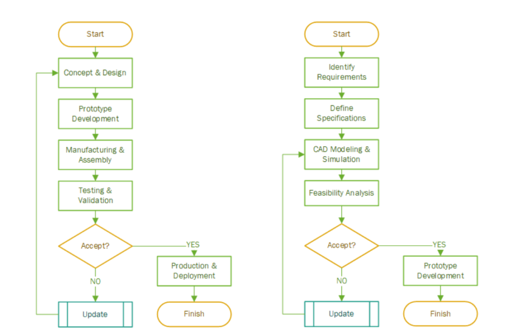
Fig. 1. UAV design and manufacturing flowchart (left). Concept and design flowchart (right)
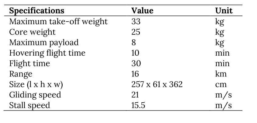
The design of the aircraft involved detailed aerodynamic analysis and mechanical design. Various iterations were performed to achieve the final design. The starting goal is to design a UAV that can deliver books from the Faculty building to the main library (7.78 km). For flights involving low Reynolds number, we used XFLR5 software containing CFD to obtain an aerodynamic database for trim analysis and non-linear simulations. XFLR5 uses XFOIL (Drela and Young, 2013) to perform direct or indirect airfoil analysis. For the aerodynamic analysis of the wing and tail, the XFLR5 program with the Vortex Lattice Method (VLM) and the Panel Method were used. Comparing takeoff speed and stall speed, or wings with different airfoils could be possible. Aerodynamic analysis of the body was performed with CFD in Simscale (SimScale, 2023). Figure 2 presents the rendered aircraft. The final UAV specifications are given in Table 2. The flight time in helicopter mode is estimated to be 10 minutes and the hybrid flight time is approximately 18 minutes. Considering the 21 m/s gliding speed, which was also chosen as the design criterion, the range was estimated to be approximately 16 km, regardless of the transceiver restriction. This range, when the coordinates between the faculty building and main library are calculated, which is 7.78 km, is sufficient considering that the drone takes off from these settlements.
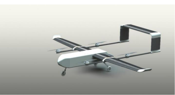
Fig. 2. Rendered image of the hybrid aircraft
Table 2. UAV aircraft specifications
The aircraft’s interior design and the package drop doors are visible in Figure 3. This aircraft has been designed to drop packages, which are small drones that can move to delivery locations as they are dropped from the aircraft. The designed package drone is shown in Figure 4. Before manufacturing, we created a mathematical model that describes how the aircraft moves. This model includes factors like air resistance, wind, engine power, spinning parts, and gravity. With simulations, we verified its performance and designed algorithms to determine the best way to control it. Once the design was finalized, we created CAD drawings of all the parts.
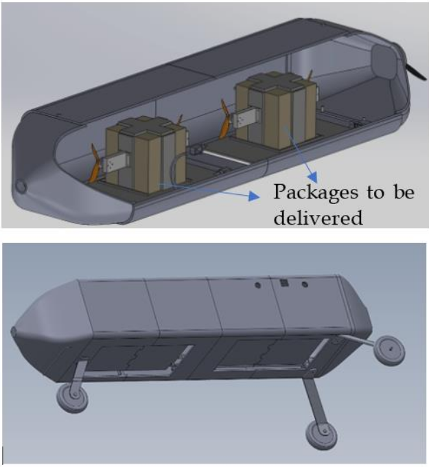
Fig. 3. Inside of the hybrid UAV aircraft body (up). The package-drop doors and landing gear (down).
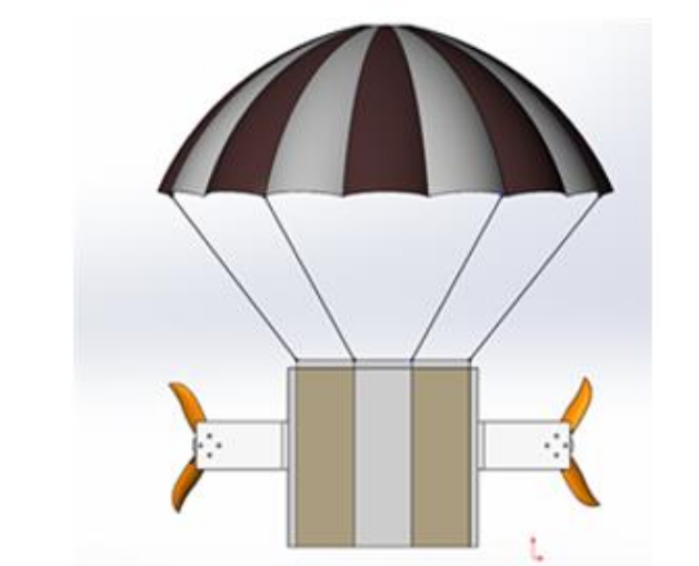
Fig. 4. Small package delivery drone to be carried inside hybrid UAV
3. Manufacturing of the Aircraft
3.1 Composite Manufacturing
Considering its strength and weight characteristics, carbon fiber is chosen as a reinforcement material over fiberglass. For carbon fiber-reinforced polymers (CFRP), there are numerous production methods available, including prepreg/autoclave procedures, vacuum infusion, vacuum bagging, and hand lay-up. Although prepreg/autoclave methods are frequently chosen in the industry to produce wings and bodies for a UAV, they are rather expensive in comparison to other approaches (McIlhagger et al., 2020). The product cannot obtain all of the details from the mold using the hand lay-up method, particularly where the leading and trailing edges are located. Contrarily, vacuum infusion offers an advantage over vacuum bagging since it vacuums extra resin out of the mold, greatly reducing the product’s weight. Due to the high expense of prepping small parts for the vacuum infusion process, the aircraft’s wings were created using vacuum infusion, while the control surfaces were produced using vacuum bagging. Epoxy-based gelcoat set was obtained for gelcoat application to be used on the surface of the molds and produced composite shells. This set is used for higher surface hardness than other epoxy-hardener sets and can also be used for lamination purposes. The gelcoat application is performed by mixing hardener and lamination resin for about 5-10 minutes with a specified mixing ratio by the company which is the ratio of 100:40 in our case. Because the density of the hardener is lower than the resin, one must put the hardener in the mixing bowl first to mix the resin and hardener perfectly. Also, during the mixing operation, all walls of the bowl should be checked if there is an unmixed region in the mixture. Otherwise, after applying the resin, some parts may not cure completely. After the mixing process, the mixture should be kept waiting for degassing which is caused by the mixing process. If there is a vacuum pump and sealing equipment in the working environment, one can use the pump for the degassing process. Right after the mixing process, an exothermic reaction occurs in the mixture and when the temperature slightly rises relative to room temperature, the resin can be applied. The gelling duration is about 20 minutes for this type of gelcoat and the operation must be finished by that time. A Lamination set was obtained from the composite market for lamination and resin infusion processes. The mixing operation is similar to the gel coat application. For preparing lamination set to its application, the ratio is determined as 100:25. The gelling duration is about 2 hours for this type of resin which makes the resin applicable to resin infusion. Also, the viscosity is lower than the gel coat resin to reduce head loss while vacuuming the resin from the resin line to the vacuum line.
3.1.1 Resin infusion process
The resin is vacuum-drawn into a dry fiber laminate in a one-sided mold during the resin infusion process. The mold perimeter is covered with and sealed with a stiff or flexible film membrane. The method of resin infusion is regarded as a closed mold process. Relative to hand lay-up and vacuum bagging composite manufacturing techniques, this is more expensive in terms of material used, time, and labor work. In Figure 6, the blue line is the vacuum line through which the resin is pulled to the catch pot (purple arrow), by the vacuum provided by the vacuum pump (blue arrow). The catch pot is connected to the vacuum line and the vacuum pump is connected to the catch pot with a PVC hose. The purpose of the catch-pot is to catch excessive resin for the pump to prevent damage. The red line is the resin line which the resin is fed into the mold. Also, the red arrow shows the sealing tape, also called gum tape. It is stuck to the mold and the bag so that it prevents air leakage.
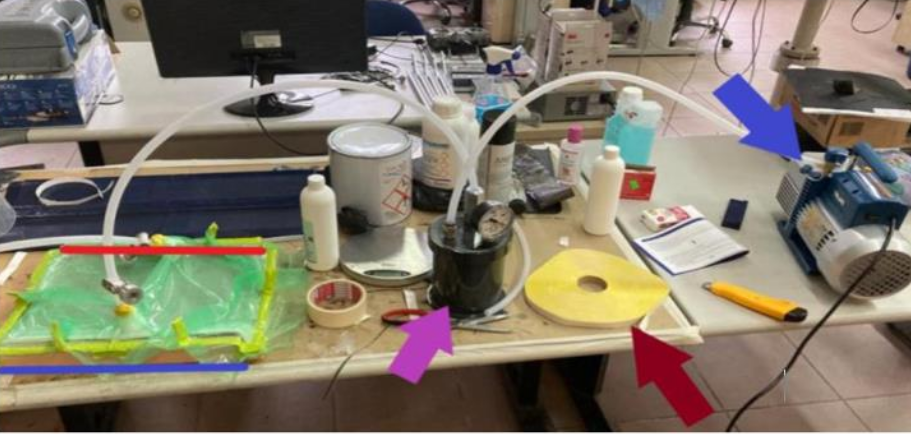
Fig. 6. A normal setup for the resin infusion process
Detailed steps are as follows:
-
Apply release agent to the mold: In this project, a PVA release agent is used. It is applied three times with 30-minute time intervals.
-
Apply gum tape (bagging tape) around the mold.
-
Place reinforcement material into the mold: The wing and tail composite shells are produced using three layers of reinforcement material.
-
Tape or glue reinforcement material to hold it in its place: Taping can work for products with simple shapes. However, if there are any complex shapes or sharp edges on the product, it might be better to use spray adhesive to stick the reinforcement material on the mold. Also, using spray adhesive causes imperfections on the surface finish of the product.
-
Cut, place, and tape a layer of peel-ply on reinforcement material: It should be cut to cover all areas between the bagging tape and should not be over-stretched.
-
Cut and place infusion mesh around the size of the bagging tape: Infusion mesh is used to create a void in the mold to reduce head loss and if the mold is relatively large, the second layer of infusion mesh can be placed where the flow of the resin cannot be reached.
-
Cut and place the infusion spiral on top of the infusion mesh: The infusion spiral is used for the same purpose as the infusion mesh. But, it has relatively more voids in it and resin can flow more easily inside of the spiral mesh. It is used to change the flow shape to a V-shaped flow.
-
Cut and place the vacuuming mesh on the vacuum line: If the vacuuming mesh is unprocurable, then 2–3 layers of infusion mesh can be placed on the vacuum line. This step is necessary for flow to reach every spot on the vacuum line.
-
Place and tape silicone connectors on the vacuum line and resin feed line.
-
Cut the bagging film oversize to allow pleating: Pleats provide an extra surface so that bagging film can cover all surfaces on the mold. Otherwise over stretching of the bagging film occurs. In addition to this, in this process, the bagging film should be checked if there are any small holes in it.
-
Stick the bagging film to the gum tape by stretching adequately to prevent any void between the bagging film and the gum tape.
-
Cut PVC hose for resin feed line and vacuum line, circling gum tape 3–4 times at the end of the hose. Then place the vacuum clamps on the hoses.
-
Cut a small hole in the bag where the inlets of the vacuum connectors are and connect the hoses to connectors on the resin feed line and vacuum line, by firmly pushing.
-
Connect the hose for the vacuum line to the catch-pot and then connect the catch-pot to the vacuum pump. Catch-pot should already be leakage-free and it should have been tested already.
-
Close air entry in the resin feed line by using the clamp.
-
Evacuate the vacuum bag by using the vacuum pump: Then, the vacuum line must be closed by using another clamp, closing the PVC hose between the vacuum pump and catch-pot.
-
Turn off the vacuum pump and check the sealing if there is any leakage on the setup. It can be followed by using the barometer on the catch-pot.
-
If it is ensured that the mold is completely sealed, mix epoxy resin with its hardener: To allow excess resin in hoses and the catch-pot, the weight of the epoxy resin should be around 1.5 times of weight calculated regarding resin consumption of the reinforcement material.
-
Allow the resin to degas for around 10 minutes.
-
Turn on the vacuum pump and release the clamp on the resin feed line to start the infusion.
-
Use the clamp to close the resin feed line when the resin reaches to catch pot.
-
Wait around 10 seconds and then clamp the vacuum line.
-
Turn off the vacuum pump and leave the part to cure for 24 hours.
In Figure 7 the catch-pot is shown after the process is complete. The catch-pot is sealed with gum tape, and a plastic container is placed inside it to collect excess resin and to prevent curing on the catch pot. Additionally, the vacuum pressure is around 700 mmHg, which is also used to check for any leakage in the bagging film.
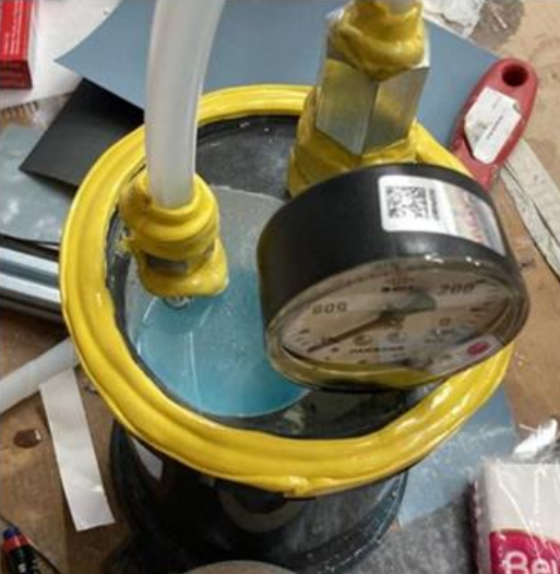
Fig. 7. Catch-pot after the process is done
In the resin infusion process, after applying the release agent to the mold cavity, the reinforcement materials, peel ply, release film, and infusion mesh are positioned. Next, the spiral tubes are placed to achieve the desired flow shape. The setup, as illustrated in Figure 8(a), is completed by following the aforementioned steps. It is essential to establish a V-shaped flow to ensure complete wetting of all areas. The V-shaped flow is depicted in Figure 8(b) during the process.
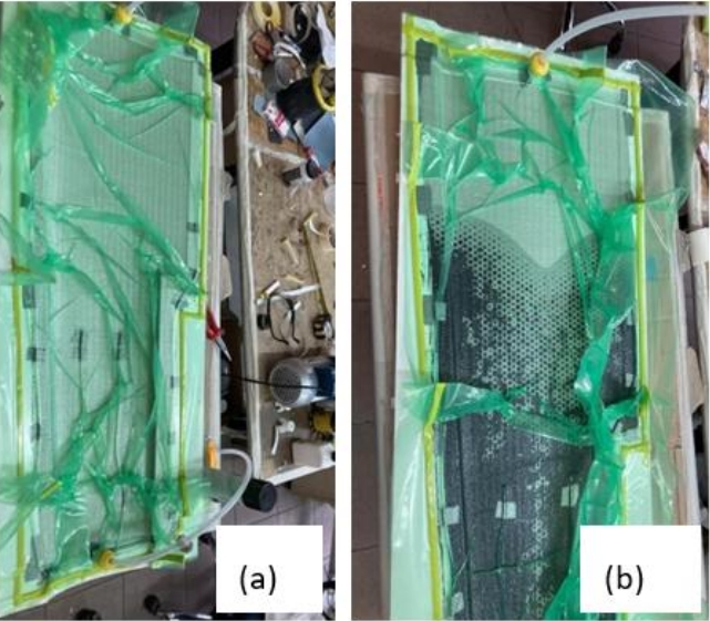
Fig. 8. Resin infusion process (a) Setup. (b) V-shaped flow
Finally, the setup is finalized by sealing the vacuum bag. To prevent excessive stretching of the bag, an appropriate number of pleats should be formed. Another crucial aspect is inspecting the sealing tape and vacuum bag for any leaks. Leak detection should be performed using a barometer located on the catch pot or a dedicated leak detector. If no leaks are found in the setup, the resin is prepared and degassed, and the infusion process is initiated by activating the vacuum pump. The resin flows from the feed line to the vacuum line. Once the resin reaches the vacuum line without any dry areas on the reinforcement material, clamps are applied to both lines to compress the tubes and maintain the vacuum after the process concludes (Figure 9(a)). In Figure 9(b), there are no dry areas present in the mold. The part is removed from the cavity once the resin has fully cured. Figure 10 illustrates the manufactured component.
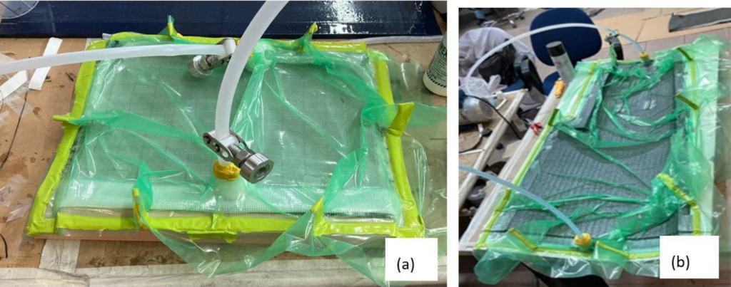
Fig. 9. (a) Curing another part. (b) Finished
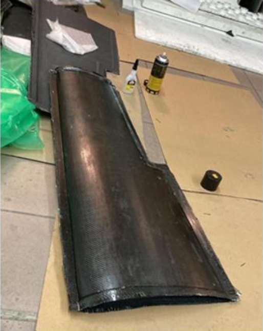
Fig. 10. A composite shell part manufactured using resin infusion technique
While removing the product from the mold, one should be very careful not to damage the products. Even though the release agent is applied perfectly to the mold before the resin infusion, it can be very hard to remove the product, especially if the mold has sharp deep edges. One might use a spatula and wooden wedges to remove the product and slow down around sharp deep edges.
3.1.2 Hand lay-up
Hand lay-up is one of the easiest techniques in composite manufacturing. It is used when the parts to be produced do not have complex shapes and do not require lightness. In this paper, the process is used to produce composite shells of rudders. The process is explained as follows:
-
Cut the desired number of reinforcement materials and one layer of peel ply. The size of the peel ply should be larger than the reinforcement material.
-
Calculate the weight considering the resin consumption of the reinforcement material.
-
Apply the release agent, as described in the previous section.
-
Mix the resin with its hardener in an adequate ratio, as described in the previous section.
-
Degassed for 10 minutes and then, using a brush, wet all surfaces of the mold with resin where the reinforcement material will cover.
-
Layer the first ply of reinforcement material on the mold and apply the resin on the reinforcement material with a brush. The pressure of the brush applied on the reinforcement material should be perpendicular to the mold to avoid displacing the reinforcement material.
-
Repeat the previous step for the desired number of reinforcement material layers.
-
Layer the peel ply on top of the reinforcement materials and apply pressure to the peel ply with a brush to remove excess resin.
-
Leave the part to cure and remove it after 24 hours.
3.1.3 Vacuum bagging process
The vacuum bagging process is an extension of the hand lay-up technique. Before initiating the process, a bagging film is cut to a size that is double the dimensions of the mold. The film is then folded in half, and sealing tape is applied to the edges of the lower half. After applying the release agent and preparing the reinforcement materials, epoxy resin is applied using a brush, initially to the mold cavity and subsequently, layer by layer, to the reinforcement materials. The peel ply and breather are then placed on top of the reinforcement material, and the setup is sealed with bagging film and sealant tape (Figure 11). The breather is used to spread the vacuum throughout the mold. The pump is used to evacuate air, and a clamp is used to close the hose. Part cures in around 24 hours. After that, the component is removed from the cavity. The aileron and elevator parts are manufactured using this technique.
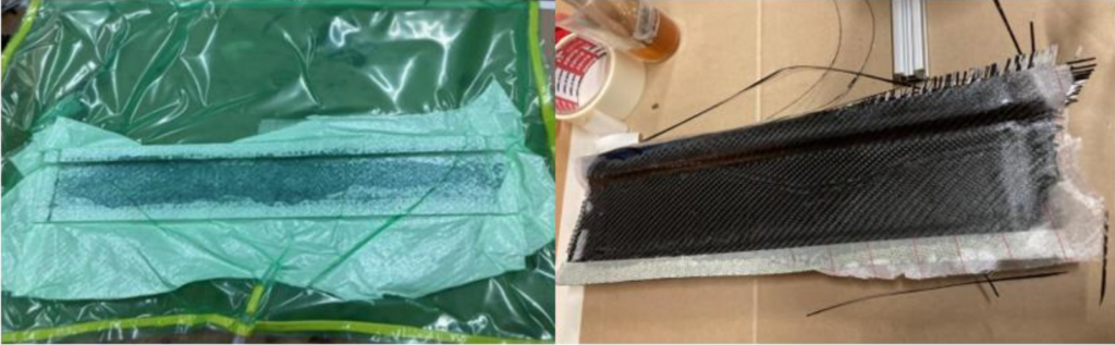
Fig. 11.Vacuum bagging process
3.1.4 Post-processing and assembly
After removing any parts from the mold regardless of which manufacturing technique is used, there will be some undesired sections on the edges of the product that should be removed before assembling them (Figure 11). Unwanted areas of composite parts are cut off and ground with a hand rotary tool once production is complete. Balsa plywood and carbon tubes form the main structure of the wings. A CNC laser cutting machine was used to cut the balsa ribs. The carbon tubes are then placed and, initially, glued to the ribs using epoxy adhesive to provide alignment for all of the ribs. After the epoxy adhesive is cured completely, the ribs are glued to the first composite shell. It will be useful to apply one layer of reinforcement material to the joint edges where it will be within the wing. Then, the second shell is attached to the ribs. If necessary, the connection edges must be ground down when the epoxy adhesive has fully dried.
In Figure 12, not only the structure of the main wings but also the assembly of the wings is shown. Because each side of the main wing consists of two sections and the second section is removable from the first section, they are connected to provide alignment for each section during the assembly process. Also, to make the assembly process easier, chamfers are created on the holes of the balsa ribs where the carbon-fiber tube profiles are inserted.
3.2 Mold design and manufacturing
Molds are used for CFRP manufacturing of wings, tail, and control surfaces. Two different techniques are used for mold manufacturing. Relatively small molds were produced using a 3D printer with PLA filament (Figure 13) to reduce time and material costs.
If a mold is bigger than the 3D printer volume, it is separated into pieces, manufactured, and combined afterward. Voids located at the joint edges are filled with polyester putty after it dries. Filling these voids is critical because epoxy gel coats are not thick enough to fill them, which can later cause leakages during the vacuuming process. Then, the whole mold is sanded until the height difference between each layer flattens and obtains a very smooth surface. This process starts with 80-grit sandpaper and progresses to 1000-grit. Finally, the mold is coated with a gel coat to make the composite shell surface smooth and shiny. The rudder mold after sanding and gelcoat process is shown in Figure 14.
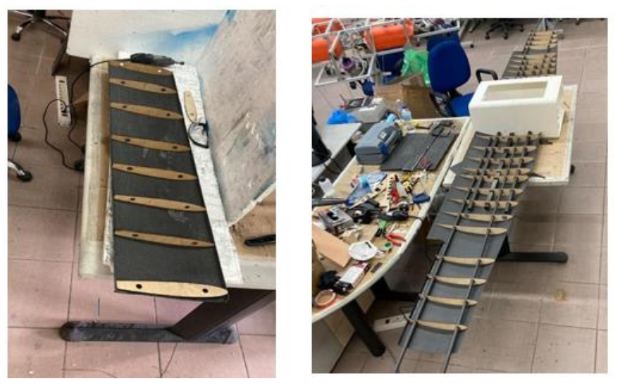
Fig. 12. Assembly of the horizontal tail wing and the main wing
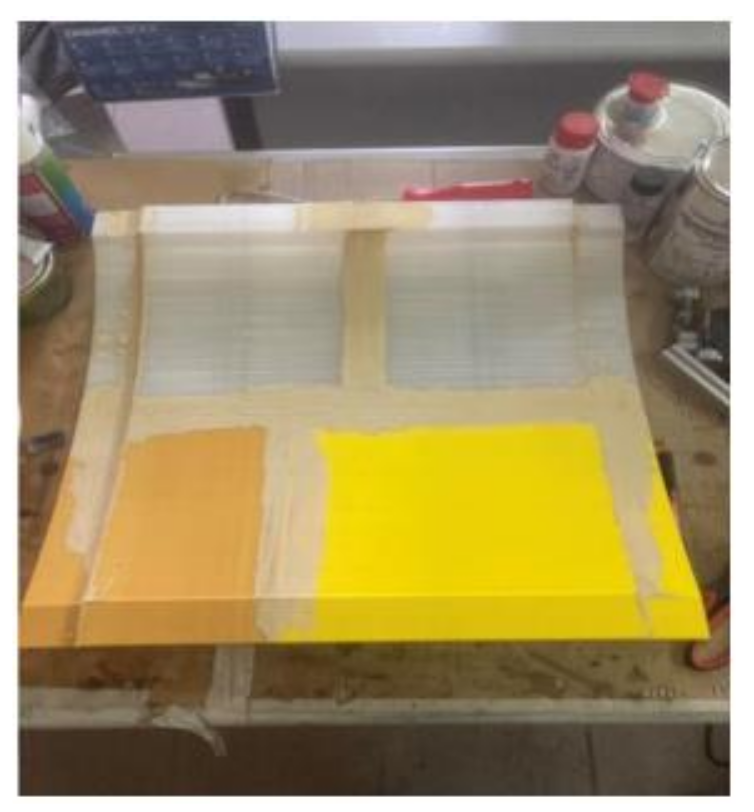
Fig. 13. 3D printed mold
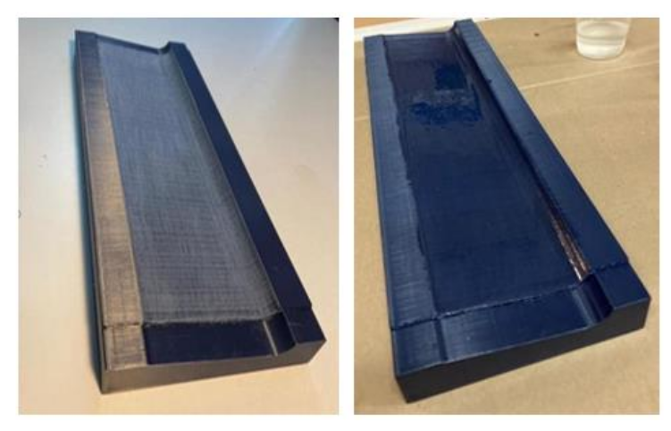
Fig. 14. Rudder mold: (a) After sanding. (b) After gelcoat
Additionally, significantly bigger molds are manufactured by processing laminated medium-density fiberboard (MDF) wood (Figure 15). For this process, MDF wood plates should first be laminated. MDF plates are stacked to the desired height while gluing them to each other with wood glue. Plates are held for 24 hours to allow the glue to dry. Then, they are processed with a CNC milling cutter. The MDF molds should be varnished as soon as possible to avoid swelling due to moisture. Once the varnish dries, the paintwork operation can be started. The raw surface of the molds is sanded until it is very smooth, gradually increasing the grit number of the sandpaper at each step. Then, acrylic paint is applied to the mold. After it dries, the painted surface is sanded again. This process is repeated until the paint reaches six or more layers. For the final layer, the paint should be sanded with a 3000-grit number sandpaper until the surface is shiny. Once it gets to this state, wax polish is applied to the mold’s painted surface with a piece of cotton or cloth. Since this process will erode the paint a little bit, it must be ensured that the paint thickness is enough for wax polishing. After wax polishing, the molds should be glossy.
3.3 3D Printing (AM)
The 3D printing technique is widely used in the manufacturing of wing and tail connection parts, body panels, brushless direct current (BLDC), servo motor connection parts, molds, etc. (Figure 16). All the parts are manufactured using an FDM 3D printer with a PLA filament. A Creality CR-10S4 3D printer at the laboratory was used for manufacturing. The parts were designed using the Solidworks CAD program. Subsequently, the part files were converted to stereolithography (STL) files. The STL files were sliced into layers, and then Gcode files were obtained for manufacturing using the Cura program. To maximize the payload, the prototype must be lightweight but durable enough to withstand impact forces during landing. Parameters were set to keep a balance between these specifications. Octoprint was used as a 3D printer interface on a Raspberry Pi computer. This allowed prints lasting more than a day to be monitored over the Internet.
In this study PLA and light weight polylactic acid (LWPLA) materials were used for additive manufacturing. Table 3 shows the comparison between PLA and LWPLA. PLA material is mostly used for molds, fittings, and other parts that require strength. On the other hand, LWPLA material is used for fuselage panels, horizontal tail connection parts, etc. LWPLA may form bubbles at a rate that varies depending on the printing temperature. As the temperature increases, the amount of bubbles increases; therefore, the density of the part changes. The weight can be reduced by up to 65% compared to the same volume without foam. This approach reduces the weight compared to regular PLA, but also decreases strength. This material has a density of 0.4 to 1.24 g/cm³ and a glass transition temperature of 55 to 60 °C. To optimize the three parameters mentioned above, the tip temperature was set to 235 °C, and the flow rate was set to 45%. Extrusion temperature, layer height, print speed, and infill density were selected to achieve strong interlayer bonding and strength. Since LWPLA material is expensive, it is only used when necessary.
Table 3. Comparison table between standard PLA and LWPLA
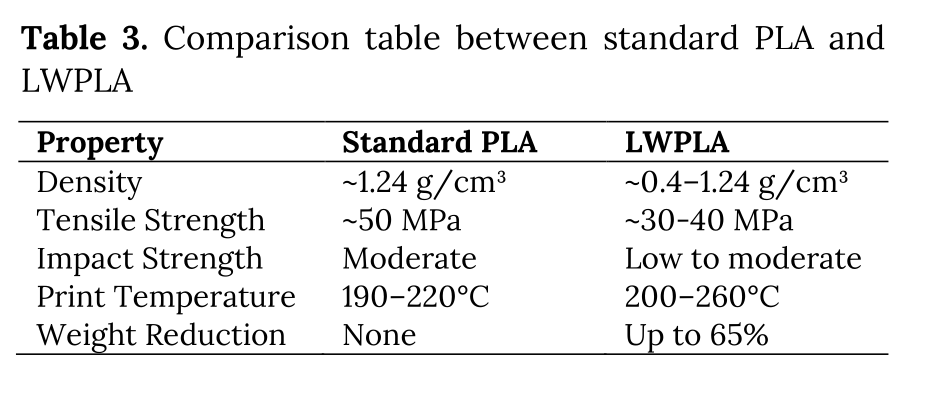
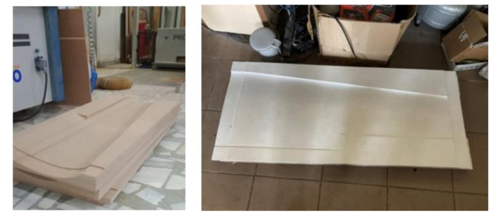
Fig. 15. MDF wood molds after CNC milling (left). After varnishing and paintwork (right)
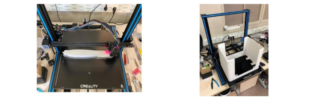
Fig. 16. 3D printing of winglets (left) and the aircraft body (right)
Most of the 3D parts were used as a mold for composite manufacturing. The durability and strength of these parts were considerably high. Some smaller parts on the aircraft such as package doors were made with PLA. Their strength and durability were acceptable for the application. To speed up the manufacturing process, and to lower the weight of the aircraft we used LW-PLA as aircraft body material. Although its tensile strength depends on foam selection, it is in the range 30-40 MPA (lower than standard PLA). We determined that the LW-PLA is not suitable for structural or load-bearing components, and for high-temperature applications. We added additional carbon rods along the body to increase the structural integrity.
3.5 Manufacturing Landing Gear
The landing gear was designed to be manufactured from aluminum 6061. It is designed by inspiring fixed-wing aircraft so that it would also have the ability to land on a runway. Considering the potential stress in usage and the weight of the landing gears, a suitable value of 6 mm was selected as the thickness of the landing gear. Plates are cut by a CNC laser cutting machine, and then they are bent by a folding machine with a 6.5 mm cavity. In the design, some elliptical holes are made to make the landing gear lighter. Also, three aluminum shafts are manufactured using a turning lathe for landing gear (Figure 17). The tires are installed on the shaft using stoppers.
3.6 Assembly of the Aircraft
The carbon-fiber composite shell of all aerodynamic surfaces (main wing and tail wing parts, control surfaces) is assembled by positioning balsa ribs inside the composite shell. The structure of the aircraft, which provides rigidity and strength, is made of carbon fiber profiles and balsa profiles assembled inside composite shells mounted on the carbon-fiber structure (Figure 18). The propulsion system and other actuators like servo motors are mounted on wings and structures using 3D printed parts. Carbon fiber profiles are used throughout the aircraft’s structure to ensure lightness. These products are produced by the pultrusion method and are relatively strong materials. The largest profile is a tail beam with a 30 mm diameter tube. It is deliberately selected to avoid buckling on the wing structure while controlling yaw angle and rate. Additionally, the main wing is supported by two circular, 24 mm diameter and one 30×30 mm square CFRP profile along the body and the first two sections of the wings. The second sections of the wings and tail are supported using 16 mm and 12 mm diameter circular tube profiles, respectively. To make the aircraft as portable as possible, the second sections of the wings, the entire tail, and the tail beams are designed to be removable.
Figure 19 presents the wings, tail, body, and other parts to be assembled into the aircraft. The motor, propellers, servos, and other electronic elements are assembled in Figure 20.
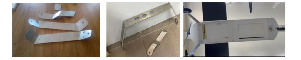
Fig. 17. Landing gear. Version-1 (left). Version-2 (middle), Installed landing gear (right)
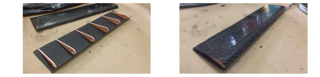
Fig. 18. The horizontal tail wing’s assembly steps
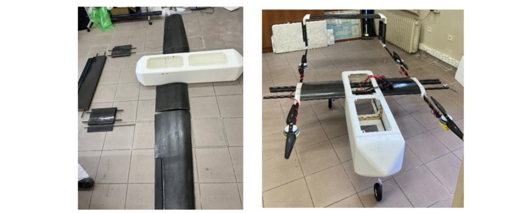
Fig. 19. The Hybrid UAV in the assembly phase (left). Partially assembled plane (right)
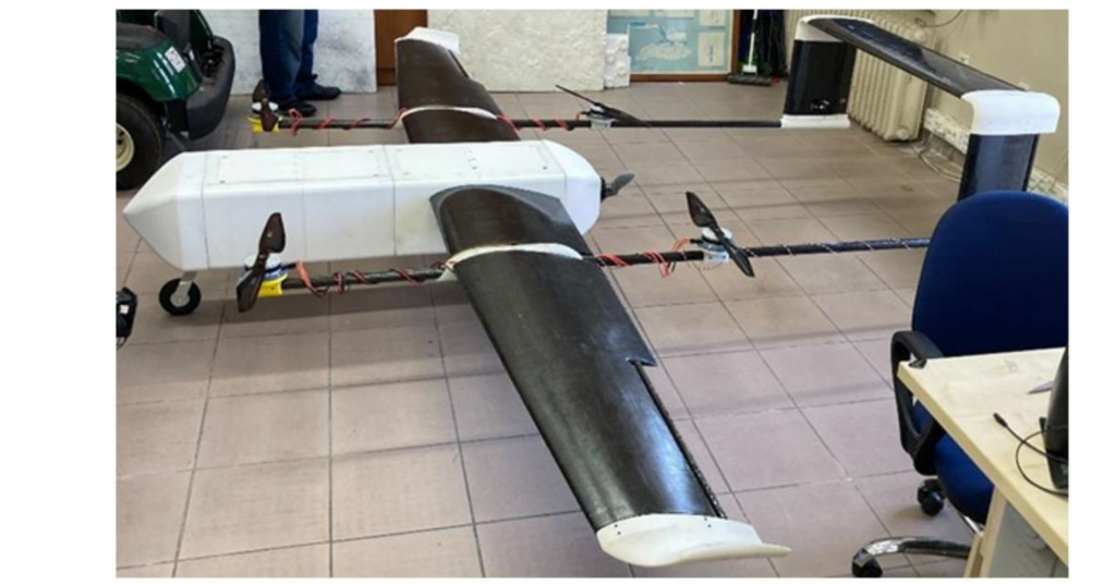
Fig. 20. Manufactured Hybrid UAV prototype, with wings and electronics
4. Final Remarks
Table 4. Delivery cost and delivery times comparison
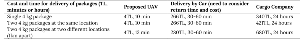
The proposed system offers benefits in two key aspects: the cost saving and flexibility due to the proposed manufacturing approach and the savings on delivery time and costs.
The manufacturing cost of the system was approximately 15,000 EUR (as of 2023), including material, electronics, and personnel costs. We obtained a price quote for manufacturing the composite wings and control surfaces at a discounted rate of 22,000 EUR. It is expected that if we had opted for traditional manufacturing, the prototype would have cost at least two to three times more.
Unlike previous work that requires time-consuming UAV landings and take-offs for package delivery, this work proposes a hybrid UAV and intelligent packages for targeted package delivery. Moreover, the aircraft can carry two packages simultaneously. This approach results in significant benefits in terms of delivery time and cost. Considering the initial design criteria for making deliveries between the faculty building and the main library (7.78 km), Table 4 presents the advantages of the proposed system. With a 12S LiPo battery that has a 20Ah capacity, an %85 charging efficiency, and an energy cost of 3.11TL/kWh, the energy cost per delivery is estimated to be approximately 4TL. The system can be ready for a new delivery within 25 minutes using a battery swap. The system is superior in both delivery cost and delivery time.
5. Conclusions
This study explores the potential of AM combined with composite manufacturing techniques for rapid manufacturing of a 3.8-meter wingspan hybrid UAV. The system consists of a hybrid aircraft and a parachute drone to be delivered. After explaining the goals of the aircraft, the aerodynamic and mechanical design to develop a UAV has been explained. The manufacturing techniques involved both FDM printing and composite manufacturing. The aircraft body, as well as molds for producing wings, were fabricated with a 3D printer. Control surfaces were manufactured using the vacuum-infusion method. Post-processing operations and assembly of the aircraft are explained. Built prototype has been used in experiments, and determined to be a reliable aerial platform.
The primary advantage of additive manufacturing (AM) lies in its ability to create lightweight, optimized structures that maintain or enhance strength and performance while minimizing the number of components required. During the research and development phase, this technology facilitated faster design iterations and enabled rapid manufacturing. By reducing the need for multiple parts and minimizing material usage during production, AM significantly reduces waste and contributes to a lower environmental impact. The findings of this study indicate that even large-scale aircraft can be built with this approach. Our future work will involve outdoor experiments focusing on algorithm development and system integration.
The novelties of the paper are as follows:
-
This work presents a novel approach to UAV cargo delivery. Unlike previous work that requires time-consuming UAV landings and take-offs for package delivery, this work proposes a hybrid UAV and intelligent packages for targeted package delivery. Moreover, the aircraft has been designed to carry two packages at a time. This approach promises accurate and fast package delivery.
-
Although there are some aircraft that were built with AM, this work demonstrates that it is possible to manufacture a bigger 3.8-meter wingspan hybrid UAV, using standard laboratory resources. Therefore, it highlights the potential of combining AM with traditional composite manufacturing techniques to produce complex UAV components.
-
This work provides a detailed account of the UAV development process, including the design, manufacturing, and assembly phases, which could be useful as a reference for other researchers.
-
The work presents findings confirming the reliability of the 3D-printed UAV as a robust platform, suggesting that 3D printing can make UAV manufacturing more accessible and efficient, potentially accelerating the advancement of UAV technologies.
Nomenclature
AM : Additive Manufacturing
BLDC : Brushless Direct Current
CFD : Computation Fluid Dynamics
CFRP : Carbon-fiber reinforced polymer
CNC : Computer numerical control
FDM : Fused Deposition Modelling
LW-PLA : Light Weight Polylactic Acid
MDF : Medium-density fiberboard
PLA: Polylactic acid
UAV: Unmanned Aerial Vehicle
VIP: Vacuum Infusion Process
VLM: Vortex Lattice Method
VTOL: Vertical Take-off and Land
References
-
3D printing industry, 2016. Royal Navy Launches the first 3D printed airplane. [Online] Available at: https://3dprintingindustry.com/news/royal-navy-launches-first-3d-printed-airplane-76767 (Accessed 4 October 2024).
-
Ackerman, E. & Strickland, E., 2018. Medical delivery drones take flight in East Africa. IEEE Spectrum, 55, pp. 34-35.
-
Ahmed, N.A. & Page, J.R., 2013. Manufacture of an Unmanned Aerial Vehicle (UAV) for Advanced Project Design Using 3D Printing Technology. AMM, 397–400, pp. 970–980. https://doi.org/10.4028/www.scientific.net/amm.397-400.970
-
Aktas, Y.O., Ozdemir, U., Dereli, Y. et al., 2016. Rapid Prototyping of a Fixed-Wing VTOL UAV for Design Testing. J Intell Robot Syst, 84, pp. 639–664.
-
Alves, P., Silvestre, M. A. & Rodrigues, A., 2021. Assessment of Low Cost FDM 3D Printing in Low Reynolds Number Propeller Prototyping. AIAA Propulsion and Energy 2021 Forum.
-
Baker, A. A., 2004. Composite materials for aircraft structures. AIAA.
-
Banfield, P. B., 2013. Design and Development of a 3D Printed UAV. Bachelor of Science in Aerospace Engineering Thesis Study, Oklahoma State University.
-
Biswas, P., Li, J., Heryudono, A. & Bi, J., 2018. Prediction of Printing Failure of a 3D Printed Drone Propeller using Fused Deposition Modeling. Conference Science in the Age of Experience.
-
Boutilier, J. J. et al., 2017. Optimizing a drone network to deliver automated external defibrillators. Circulation, 135, pp. 2454-2465.
-
Chaturvedi, S.K., Sekhar, R., Banerjee, S. & Kamal, H., 2019. Comparative review study of military and civilian unmanned aerial vehicles (UAVs). INCAS Bulletin, 11 (3), pp. 181-182.
-
Çetinsoy, E. et al., 2012. Design and construction of a novel quad tilt-wing UAV. Mechatronics, 22(6), pp. 723-745.
-
De Silvestri, S. et al., 2023. Challenges for the Routine Application of Drones in Healthcare: A Scoping Review. Drones, 7, p. 685.
-
DHL Trend Report. Aerial Vehicles in logistics a DHL Perspective on implications and use cases for the logistics industry. [Online] Available at: https://www.dhl.com/discover/content/dam/dhl/downloads/interim/preview/updates/dhl-trend-report-uav-preview.pdf (Accessed 4 October 2024).
-
Drela, M. & Youngren, H., 2013. XFOIL Subsonic Airfoil Development System. [Online] Available at: https://web.mit.edu/drela/Public/web/xfoil/ (Accessed 4 October 2024).
-
Esakki, B., Sagar, N., Chandrasekhar, U. & Salunkhe, S., 2019. Development of light weight multi-rotor UAV structures through synergistic application of design analysis and fused deposition modelling. International Journal of Materials and Product Technology, 59, pp. 229-238.
-
Ferro, C., Grassi, R., Seclì, C. & Maggiore, P., 2016. Additive manufacturing offers new opportunities in UAV research. Procedia CIRP, 41, pp. 1004-1010.
-
Goh, G.D. et al., 2017. Additive manufacturing in unmanned aerial vehicles (UAVs): Challenges and potential. Aerospace Science and Technology, 63, pp. 140-151.
-
Hissa, L. & Mothé, J.E.M., 2018. Development of an Autonomous UAV. 10.26678/ABCM.CONEM2018.CON18-1600.
-
Jansen, H., 2024. Impact of Toroidal Propeller Design on Unmanned Aerial Vehicle Acoustic Signature and Aerodynamic Performance. International Journal of Aerospace Engineering (IJASE), 2.1.
-
Kellermann, R., Biehle, T. & Fischer, L., 2020. Drones for parcel and passenger transportation: A literature review. Transportation Research Interdisciplinary Perspectives, 4, p. 100088.
-
Klippstein, H. et al., 2018. Fused Deposition Modeling for Unmanned Aerial Vehicles (UAVs): A Review. Adv. Eng. Mater., 20: 1700552.
-
Koetsier, J., 2021. Drone delivery is live today, and it’s 90% cheaper than car-based services. Forbes. [Online] Available at: https://www.forbes.com/sites/johnkoetsier/2021/08/18/drone-delivery-is-live-today-and-its-90-cheaper-than-car-based-services/
-
Li, Y., Liu, M. & Jiang, D., 2022. Application of Unmanned Aerial Vehicles in Logistics: A Literature Review. Sustainability, 14, p. 14473.
-
Lyu, M. et al., 2023. Unmanned Aerial Vehicles for Search and Rescue: A Survey. Remote Sens., 15, p. 3266.
-
Marks, P., 2011. 3D printing: The world’s first printed plane. New Scientist. [Online] Available at: http://www.newscientist.com/article/dn20737-3d-printing-the-worlds-first-printed-plane.html (Accessed 4 October 2024).
-
Martinez-Alpiste, I. et al., 2021. Search and rescue operation using UAVs: A case study. Expert Systems with Applications, 178, p. 114937.
-
McIlhagger, A., Archer, E. & McIlhagger, R., 2020. Manufacturing processes for composite materials and components for aerospace applications. Polymer composites in the aerospace industry, pp. 59-81.
-
McKinnon A., 2016. The Possible Impact of 3D Printing and Drones on Last-Mile Logistics: An Exploratory study. Built Environment, 42 (4), pp. 576-588.
-
MIT, 2023. A Technology Highlight Toroidal Propeller. MIT Lincoln Laboratory. [Online] Available at: https://www.ll.mit.edu/sites/default/files/other/doc/2023-02/TVO_Technology_Highlight_41_Toroidal_Propeller.pdf (Accessed 4 October 2024).
-
Mohsan, S.A.H. et al., 2023. Unmanned aerial vehicles (UAVs): practical aspects, applications, open challenges, security issues, and future trends. Intel Serv Robotics, 16, pp. 109–137.
-
Moon, S., Tan, Y., Hwang, J. & Yoon, Y., 2014. Application of 3D Printing Technology for Designing Light-weight Unmanned Aerial Vehicle Wing Structures. Int. J. Precis. Eng. Manuf.-Green Tech., 1, pp. 223-228.
-
Radoglou-Grammatikis, P. et al., 2020. A compilation of UAV applications for precision agriculture. Computer Networks, 172, p. 107148.
-
Rajendran, S. & Srinivas, S., 2020. Air taxi service for urban mobility: A critical review of recent developments, future challenges, and opportunities. Transportation Research Part E: Logistics and Transportation Review, 143, p. 102090.
-
Sebastian, T. & Strem, C., 2017. Toroidal propeller. US Patent US10836466B2.
-
Shahrubudin, N., Lee, T. C. & Ramlan, R., 2019. An overview on 3D printing technology: Technological, materials, and applications. Procedia Manufacturing, 35, pp. 1286-1296.
-
SimScale GmbH, 2022. Simscale. [Online] Available at: https://www.simscale.com/ (Accessed 4 October 2024).
-
Smirnov, A. et al., 2023. Problems and prospects for the development of urban air mobility on the basis of unmanned transport systems. Transportation Research Procedia, 68, pp. 151-159.
-
Srivastava, A. & Prakash, J., 2023. Techniques, Answers, and Real-World UAV Implementations for Precision Farming. Wireless Pers Commun, 131, pp. 2715–2746.
-
Telli, K. et al., 2023. A Comprehensive Review of Recent Research Trends on Unmanned Aerial Vehicles (UAVs). Systems, 11, p. 400.
-
Yap, Y. L. et al., 2023. Topology optimization and 3D printing of micro-drone: Numerical design with experimental testing. International Journal of Mechanical Sciences, 237, p. 107771.
-
Zlatan R., 2021. Rapid prototyping with fiber composites – Manufacturing of an amphibious UAV. Master’s thesis, KTH Royal Institute of Technology.