

Abstract |
In this study, an electronic cover system was designed and produced that will prevent forgetting before take-off at aircraft. Proposed system, which has a very simple but effective structure, basically consists of microcontrollers, wireless communication modules, and switches. This prototype system has two components, the pitot component and the cockpit component. If the pitot component is attached to the pitot tube, the system starts working when the cockpit component is active. In the designed system, both components communicate with each other wirelessly. As a result of this communication, both components flash the powerful light-emitting diodes (LEDs) on them at certain intervals (by making a flash effect). When the power LEDs are blinking, it means that the cover is attached to the pitot tube. In this way, both the marshalling officers and the pilot are warned that the cover is attached to the pitot tube, preventing a possible accident. KeywordsPitot Tube 1. Intoduction
As is known, the first people to fly an airplane with a motor for the first time in history were Orville Wright and Wilbur Wright, known as the Wright brothers. In the first plane that the Wright brothers flew, only three instruments were used to ensure a safe flight. These were the engine tachometer, anemometer, and stopwatch. However, many complex and sensitive instruments and indicators are used in today’s aircraft. Altitude, airspeed, vertical speed, magnetic direction, artificial horizon, fuel amount, fuel pressure, oil amount, oil pressure, temperature, turn coordinator, and navigation indicators are just a few of them. Among these indicators, total and static pressures must be measured for the altitude, air velocity, and vertical velocity indicators to work. Normal atmospheric pressure, which acts equally on the entire surface of an aircraft, regardless of whether it is moving or immobile, is called static pressure. However, when the aircraft is in motion, the leading edges are subjected to additional pressure to the static pressure. This pressure is defined as dynamic pressure. So, a pressure called the Pitot pressure, which is the sum of the static and dynamic pressure, acts on the leading edges of the aircraft. Pitot-static systems are used to measure these pressures, the internal structure of which is shown in Fig. 1.
Fig. 1. A typical pitot-static system and the indicators it feeds (Anonymous, 2023).
Fig. 2. Examples of pitot cover. As demonstrated in Fig. 1, the pitot tube used to measure the total pressure has an open end facing the flight direction of the aircraft. This hole, which has a very small diameter, must always remain open during the flight. Any blockage here will cause the aforementioned altitude, airspeed, and vertical velocity indicators to show incorrect values. If one of the dynamic or static ports is clogged, the Pitot tubes can overestimate the velocity by up to about 5.6% (Golparvar and Yapici, 2020). In order not to experience such a danger during the flight, there are drain holes and heaters in the pitot tube as demonstrated in Fig. 1. However, clogging of the Pitot tube can also occur when the aircraft is parked. Because dust or sand particles carried by a strong wind can block this hole even when the plane is parked. In addition, since the Pitot tube is warmer at night compared to other environments, it can also be used as a nest by small-sized creatures. Therefore, when the aircraft is parked, the protruding probe of the pitot tube should be covered with appropriate covers. There are pitot covers produced in different ways from many different materials. Fig. 2 shows various pitot covers. In order to prevent these covers from being forgotten during the pre-flight checks, a very striking streamer, flag, or strip, approximately half a meter long, is attached to them. The streamer is also seen in Fig. 2. In the pre-flight checks of the pitot/static system, the following factors are considered (CAE, 2014):
Because of the stress and overwork of the relevant personnel and the pilot, forgetting the cover is attached to the Pitot tube or using this place as a nest by small- sized creatures causes disruption of the voyage and even an accident.
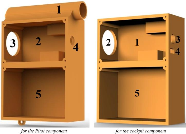
Fig. 3. Images of the Malaysia Airlines plane before and after it took off on 18 July 2018 with the Pitot cover hung up forgotten (ATSB, 2022a). For example, on 18 July 2018, an Airbus A330 aircraft belonging to Malaysia Airlines took off from Brisbane to Kuala Lumpur with all three Pitot covers hung up. When it was understood that the indicators were showing incorrectly, an emergency landing was made at the same airport by taking all risks. This status is shared in full detail in the report published by the Australian Transport Safety Bureau (ATSB) and given in (ATSB, 2022a). Fig. 3 (the view before take-off) shows that the three Pitot covers are still attached while the A330 is being pushed back. The damage caused to the airframe during the flight by the streamers attached to the Pitot covers in this short-term flight, where there was no loss of life, can be easily seen in the image taken immediately after the emergency landing and shared in Fig. 3. However, Pitot tube obstruction is not always so easily overcome. Flight 301, operated by Birgenair on 6 February 1996, with a Boeing 757-225 aircraft with the tail register TC-GEN, ended with an accident shortly after the aircraft took off from Puerto Plata International Airport. All 176 passengers and 13 crew members on board the plane, which crashed 26 km northeast of Puerto Plata, died in this crash. As a result of the research, it was understood that a small creature nested in one of the Pitot tubes of the aircraft, so the speed indicators showed differently, and the autopilot, which took the clogged Pitot tube as a reference, reduced the speed of the aircraft, so the aircraft was exposed to stalls and crashed (Hall, 1996; Ortiz, 1996). Despite these events and the precautions taken, it is known that similar events have been repeated in the recent past. For example, on 27 May 2022, an Airbus A350-941 of Singapore Airlines was to be pushed back to operate flight SQ256 from Brisbane Airport. However, minutes before pushing, it was noticed by a staff member whose job was only to refuel, that the Pitot covers were still attached. Thereupon, a licensed aircraft maintenance engineer (LAME), who should have done this work earlier, removed the Pitot covers one minute before departure time (ATSB, 2022b). When the three examples given are examined, it is possible to experience fatal accidents at any time due to the plane taking off without removing the Pitot cover, or clogging it while parked because the cover is not installed. 2. Literature ReviewAcademic studies conducted to solve the problem defined above were searched in accessible online databases using the keyword “pitot tube”. The studies reached are summarized below. Klopfenstein Jr (1998) presented a comprehensive guide to measuring air velocity and airflow using a Pitot tube. It was emphasized that the Pitot tube and air passages should be calibrated in a wind tunnel. Calibration was carried out using a standard wind tunnel and measurements were made at different flow rates. A computer-aided data acquisition system was designed, the measurement data were processed and calibration factors were applied. The article aimed to provide practical information on Pitot tube-based measurement techniques for field engineers. Dobrowolski, Kabaciński, and Pospolita (2005) presented mathematical models of flow measurement devices such as the self-averaging Pitot tube. Such flow meters were distinguished by their advantages of lower pressure losses in large-diameter pipelines, high-temperature tolerance, and easy installation. In the paper, a model was developed that analyzes the influence of the shape of the flow sensor, its structural features, and flow conditions on the differential pressure. The model was validated by calculating the velocity and pressure fields around and inside the sensor using numerical methods. The study explained the relationship between the Reynolds number and the flow coefficient and presented results applicable to metrology. Sun, Li, and Zheng (2009) investigated the effects of incorrect installation of the Pitot tube on measurement performance. In the study, the impact of installation angles on measurement accuracy were evaluated theoretically and experimentally; correction factors were developed for errors caused by the deflection angle. The findings showed that mistakes can be reduced with correction factors that are symmetrical with horizontal angles and decreasing and increasing with vertical angles. With this method, measurement errors can be reduced to less than 30% even in the case of incorrect installation. Cho et al. (2012) presented a GPS-based calibration method to improve the accuracy of air data systems used in aircraft. The study developed for the smart unmanned aerial vehicle (UAV), a tilt-rotor unmanned aerial vehicle built by the Korea Aerospace Research Institute, addresses the critical challenges in measuring airspeed, barometric altitude, and sideslip angle. Kalman filters and GPS speed information were used to calibrate the errors in static pressure measurements reflected in the airspeed and altitude calculations resulting from the placement of the pitot-static tube in the fuselage. The proposed methods were validated with simulation and real flight data of the smart UAV. Imai, Klockowski, and Varela (2013) presented a method based on error signatures to detect and correct sensor errors in spatiotemporal data streams. Error signatures are defined by mathematical models to identify data inconsistencies. The method was tested on a specific Cessna flight and the 2009 Air France AF447 accident. For the Cessna flight, scenarios, where the Pitot tube (airspeed indicator), GPS, and both failed, were simulated. The error detection accuracy was 93%, and the maximum correction time was 5 seconds. The Pitot tube failure for the AF447 accident was analyzed with real flight data. The error was successfully detected and corrected within 5 seconds. The overall accuracy was 96.31%. The developed method increased data accuracy and provided an effective solution for flight safety. In the future, the integration of this approach to larger-scale systems and autonomous aircraft is targeted. Li et al. (2014) discussed the difficulties encountered in determining and calibrating the discharge coefficient of average Pitot tubes used in large-diameter pipes where fully developed flow cannot be achieved. In particular, the effects of elbows (single elbow, double elbows in the same plane, or different planes) in the upstream flow profile were investigated by numerical simulations and experiments. Using the standard k-ε turbulence model, the velocity profiles after the elbow were evaluated, and positive and negative deviations in the discharge coefficients were observed. By comparing the simulation and experimental results, models were developed to correct these effects in the calibration of flowmeters in large-diameter pipes. Takahashi and Shimoyama (2018) designed a waterproof Pitot tube to measure air velocity during the flight of seabirds. This tube is waterproof via a nano-porous membrane and can perform high-precision measurements with piezo resistive differential pressure sensors. The manufacturing processes, sensor calibration, and experimental verification studies are detailed. The results show that the device can reliably measure air flow velocity both underwater and in open-air conditions. This innovative design contributes to airflow measurement applications in harsh environmental conditions. Hagiwara et al. (2019) presented an underwater Pitot tube developed for measuring the swimming performance of marine animals. In traditional Pitot tubes, water bubbles entering the tube inlet affect the measurement accuracy, while in this new design, the inlets are closed with thin elastic films. In addition, the incompressible liquid inside the tube and a piezo resistive pressure sensor allowed accurate measurement of the water flow rate without being affected by hydrostatic pressure during deep dives. Its compact structure is suitable for use without hindering the natural movements of marine animals. Tests showed that the device responds quickly to air-water transitions and successfully measures water flow at different speeds. Golparvar and Yapici (2020) developed a three-dimensional model to model and analyze the blockage situations of the Pitot tube. The developed model simulated the blockage situations of both dynamic and static ports. In case of blockage of the dynamic port, the sensor shows values about 5.6% above the actual speed, while blockage of the static port leads to slightly lower speed values. The study aims to contribute to the development of alternative designs to increase the reliability of these sensors and prevent aircraft accidents. Sun and Gebre-Egziabher (2020) presented a fault detection and isolation algorithm using dual Pitot tubes for the design of reliable air data systems for UAVs. The algorithm works in integration with an accelerometer (IMU), a GNSS receiver and two synthetic air data systems (SADS) and evaluates each Pitot tube independently. It detects and isolates faults with residual thresholding and decision logic based on redundancy analysis. The system also calculates protection levels against faults caused by aircraft dynamics and external factors. Simulation results have shown the effectiveness of the algorithm in developing reliable and low-cost UAV air data systems. Zhong et al. (2020) developed a method to automatically identify pitot tube caps using a UAV to prevent human-induced maintenance errors such as failure to remove pitot tube caps. In the study conducted on 36 field images, the images were processed with grayscale and color histogram extraction methods, and then errors were identified using support vector machines (SVM). SVM parameters were optimized with the cross-validation (K-CV) method and 96% accuracy was achieved. The method aims to increase the health management capabilities of aircraft pitot-static pressure systems. Kishimoto et al. (2021a) developed a compact Pitot-static tube-based water flow sensor used for biological data collection (biologging) to study the behavior of marine organisms. Due to its design based on the Pitot tube principle, it can precisely detect water flow velocity by measuring differential pressure. The developed sensor responded to water flow velocity between 0.2 and 1.6 m/s with sufficiently high sensitivity. Kishimoto et al. (2021b) presented a closed-inlet Pitot-static tube-based water flow sensor designed to study the swimming behavior of marine animals in their natural habitat. The sensor used a structure filled with incompressible liquid and sealed with silicone membranes to detect water flow velocity by differential pressure measurement. This small-sized, lightweight, and pressure-resistant sensor can measure water flow velocity between 0.2 m/s and 1.6 m/s with high precision. This design solved the long-term measurement difficulties of existing sensors and offered a practical innovation in marine biology research. Tabanlı and Yüceil (2021) discussed the design, analysis, and testing processes of a pitot-static probe to perform speed and altitude measurements of aircraft in the Mach range of 0.5-0.95. The probe, optimized using computational fluid dynamics (CFD) analysis, was tested in the ITU Trisonic wind tunnel and achieved error rates of 0.38%, 0.1%, and 0.07% for static pressure, total pressure, and Mach number measurements respectively. The probe design took into account factors such as nose geometry, pressure port placement, and turbulence effects, and observed the effects of shock waves on measurement accuracy at high speeds. The study presented a probe design capable of making accurate measurements in the subsonic and transonic regimes. Pechout et al. (2022) used a high-speed pressure difference Pitot tube as an innovative method to measure exhaust flow rate. With a sampling frequency of 5000 per second, this tube captured the high-amplitude exhaust gas fluctuations, especially seen in small engines, and provided accurate and continuous flow data, unlike traditional methods. The Pitot tube was calibrated at different engine speeds and loads, providing high-precision instantaneous exhaust flow data for emission measurements. It was shown its usability for both laboratory and real-world driving conditions in emission analyses. Ribeiro et al. (2022) presented the design and sensitivity analysis of a calorimetric solid-state thermal mass flow sensor (TMFS) operating in high-speed and high-temperature environments as a solution to the icing problems of existing pitot tubes used in aircraft air data systems. The sensitivity of the sensor was evaluated by increasing the distance between the heater and the thermal sensors and adding a thermal barrier made of Parylene-N material; it was determined that these arrangements increased the temperature change sensitivity by 80%, the speed change sensitivity by 100% and the overall sensitivity by 6 times. Simulations performed with COMSOL Multiphysics and Simulink software confirmed the improvements in the durability and performance of the sensor, and it was concluded that this design was ready for wind tunnel tests as a reliable alternative against icing. Diniz and Pacheco (2023) investigated the estimation of heat transfer coefficient (HTC) with Steady-State Kalman Filter (SSKF) to detect icing in pitot tubes in real-time. This computationally efficient method determined HTC changes with high accuracy and provided rapid recovery in sudden changes. The approach, which allows real-time monitoring and icing control, aims to increase aircraft safety and prevent accidents. It has the potential for practical use in aircraft systems by providing low-cost and fast solutions. As can be seen, there is only one study on the detection of the Pitot cover. In the study conducted by Zhong et al. (2020), image processing-based Pitot tube cover detection was attempted. In this context, images of 36 different Pitot tubes with and without a cover were taken and processed, and then the presence of the cover was tried to be determined. However, as a result of this determination, it was not shared whether the pilot was warned before the flight or how this information was transferred to the pilot. In this study by us, a Pitot tube cover with electronic components was designed. In the design made, whether the Pitot tube cover is forgotten in the Pitot tube will be determined electronically by the designed circuit. If, in the pre-take-off checks, the cover is forgotten attached to the Pitot tube (i.e. cover is not removed), the pilot will be visually alerted by a very high flux light in the cockpit. In this way, possible accidents due to forgetting the cover attached to the Pitot tube will be prevented. 3. Material and MethodIn the designed system, it is determined whether the Pitot tube cover is removed or not and the pilot is warned about this situation. Therefore, the system consists of two components. The first of the components is the cover designed to be attached to the Pitot tube and specific to the aircraft. The other is the component placed in the cockpit to warn the pilot if this cover is forgotten attached to the Pitot tube before the flight. From the moment the designed cover is attached to the Pitot tube, it will wirelessly send information to the component in the cockpit. This information sent will cause a high-intensity light emitted diode (power LED) on the component in the cockpit to light up. The illumination of the Power LED indicates that the cap is attached to the Pitot tube. There is also a power LED on the cover attached to the Pitot tube. The illumination of this LED indicates that the component in the cockpit is energized and communication is provided with it. Therefore, due to these LEDs, it can be easily understood that all system components are active and that the cover is attached to the Pitot tube. The designed system consists of electronic components and boxes in which these components are placed. For this reason, it would be more accurate to examine the designed system under two headings as electronic design and mechanical design. 3.1 Electronic DesignThe basic electronic materials used in the designed system are Arduino Nano, NRF24L01, and NRF adapter. In the study, two Arduino Nanos were used as microcontrollers both to ensure the compatibility of the receiver and transmitter circuits and to control the operation of the system. Weighing 7 grams, this microcontroller is 45 mm long and 18 mm wide. In the designed system, a low-cost wireless communication module NRF24L01 was used to provide communication between the component attached to the Pitot tube and the component placed in the cockpit. Since there is mutual communication between the two components, both components work as both receiver and transmitter. This module, which has a power amplifier and a surface-mounted antenna, provides wireless communication 2.4 GHz up to 100 meters in the open area. The operating voltage of NRF24L01 is in the range of 1.9V to 3.6V. An NRF adapter was used both to provide this required voltage and to ensure that the module worked more stably. Besides these basic electronic components mentioned above, power LEDs, resistors, semiconductor switches, and mechanical switches were also used. In addition, during the trial of the design, 12V-3Ah batteries were used because we did not have any permission to interfere with the electrical system of the aircraft. The schematics of the circuits that are formed using these electronic materials are shown in Fig. 4. Normally, one jack is connected to the batteries in parallel so that they can be charged. However, these jacks are not shown in the circuit diagrams in Fig. 4. The switch in the component to be attached to the Pitot tube is a wheeled limit switch. This switch was used to automatically ensure that the circuit was powered and started working as it should when this component was attached to the Pitot tube. Therefore, no external switch was used to manually open and close the circuit. The activation of the component to be placed in the cockpit could also be done automatically via the master switch on the aircraft, without the need for any manual switch. However, since we do not have any permission to interfere with the electrical system of the aircraft, the activation of the cockpit component is carried out using a normal on-off switch. Therefore, the materials and wiring diagrams used in both circuits are almost the same, except for the switches. In the software of the designed system, a password was used to ensure that only the system components belonging to the same aircraft matched with each other. In this way, it has prevented different aircraft send information to each other and the system works incorrectly. 3.2 Mechanical DesignIn order to mount the electronic circuits detailed above to the Pitot tube and the cockpit, two boxes were designed in the program called Solidworks. These designed boxes were produced using a 3D printer. A solid model image of the cover to be installed to the Pitot tube of the aircraft is shown in Fig. 5. This box, which has 106x160mm dimensions, was designed as a normal Pitot tube cover. In other words, it is capable of preventing dust and small creatures from entering the Pitot tube while it is attached to the aircraft. The cylindrical section highlighted by number 1 in the Pitot component is such that this box is fitted to the Pitot tube of the aircraft to be tested with appropriate tightness. In addition, this section is designed to be suitable for the operation of the wheeled limit switch mentioned above. The chamber shown by 2 is the section where the designed electronic circuit will be placed. The circle numbered 3 in this chamber is for the placement of the power LED. The circle indicated with number 4 is for plugging the jack to be used while charging the battery. The chamber shown with 5 is for the placement of the battery that will supply the relevant circuit. The ring on the bottom surface of the box was created for attaching the streamer with “Remove before flight” written on it.
|
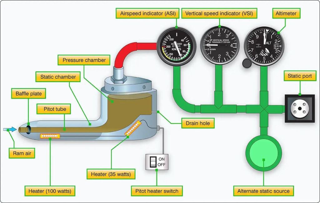
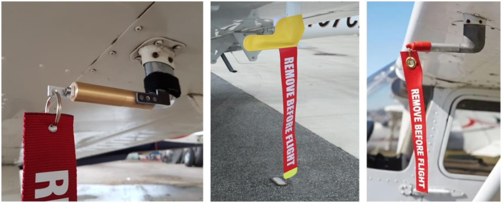
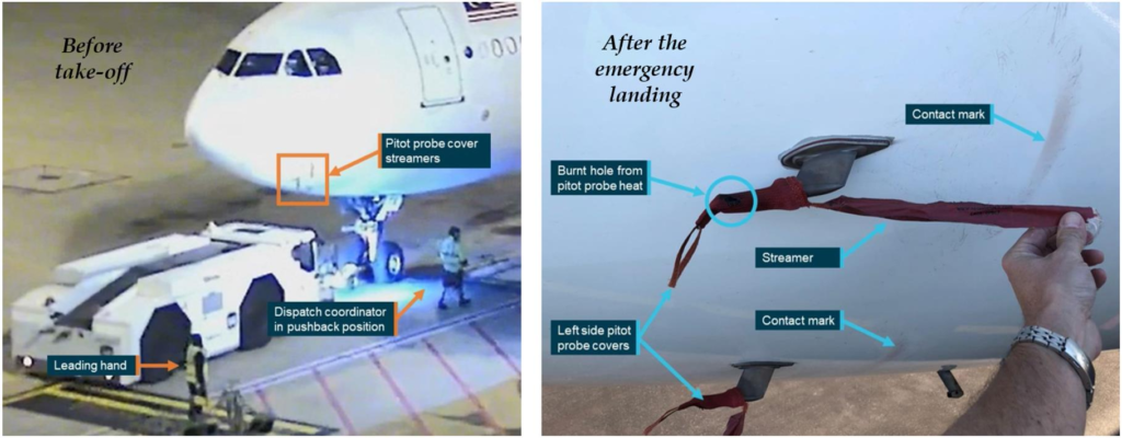
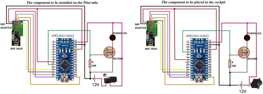
Fig. 4. The circuit diagrams of the designed system
4. Experimental Studies
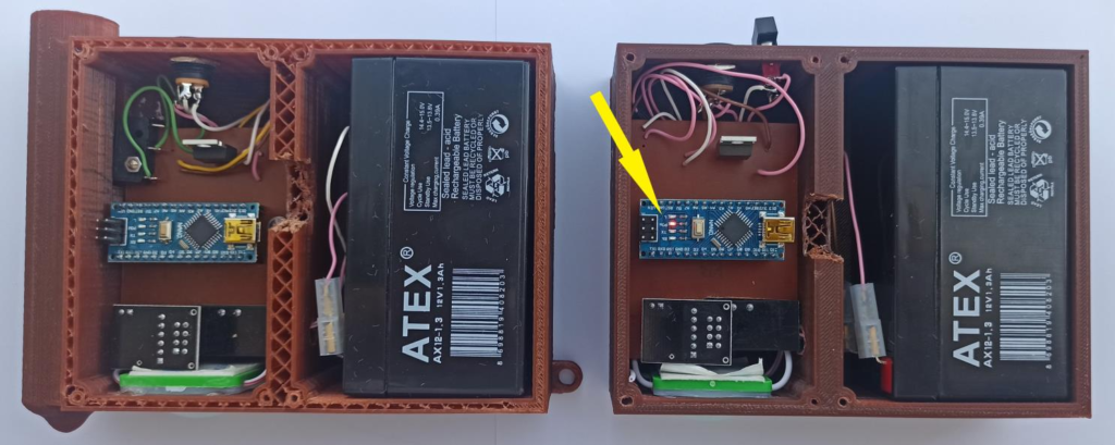
Fig. 6. The case that only the cockpit component is active in the designed system.
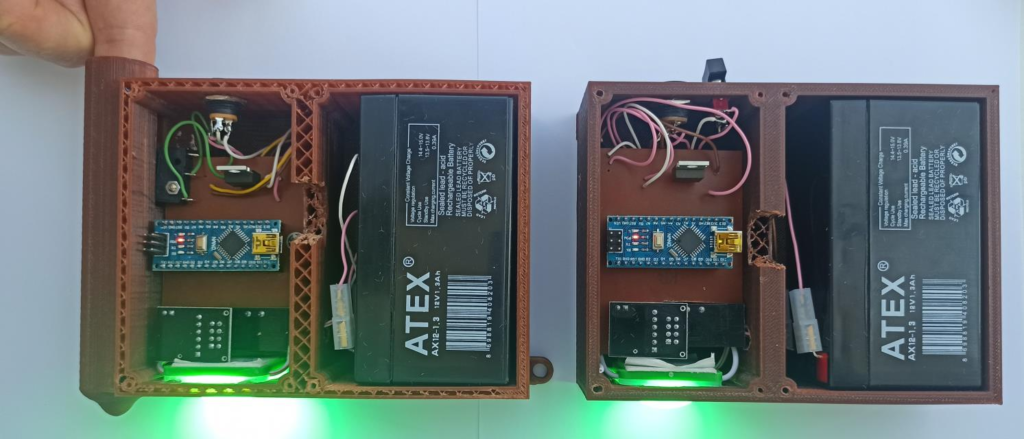
Fig. 7. The case that both components are active in the designed system.
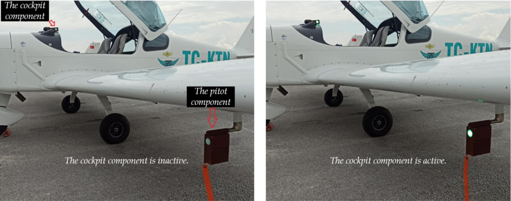
Fig. 8. The cases where the cockpit component is passive and active on the Viper SD4.
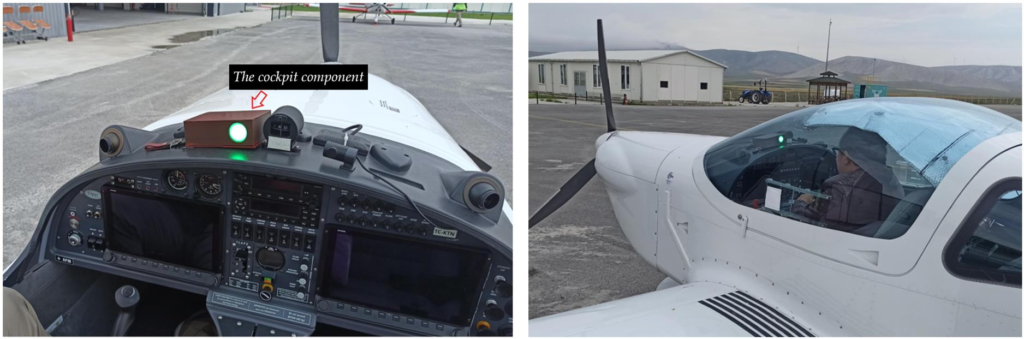
Fig. 9. The views of the cockpit component from inside and outside of the cockpit on the Viper SD4 (the switch is at the ON position).
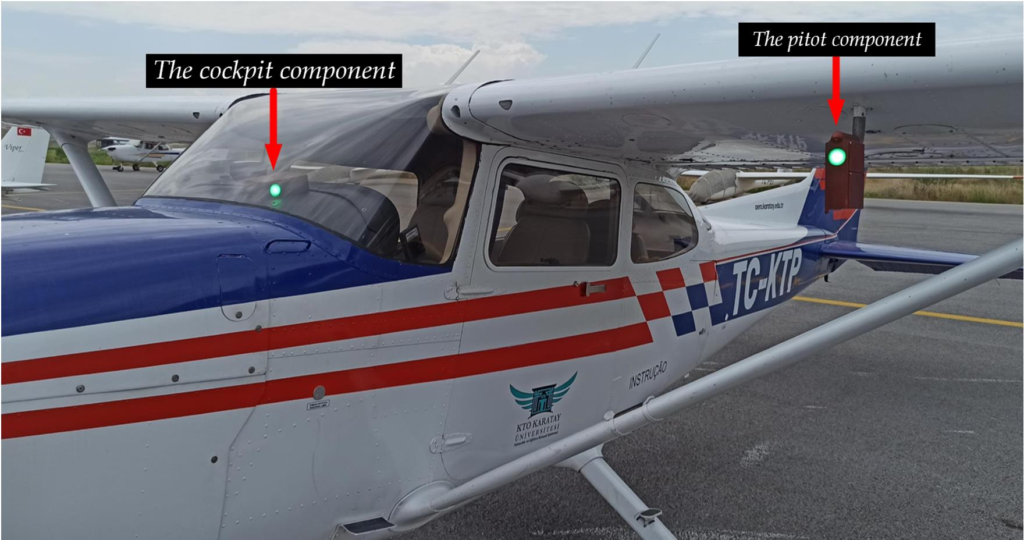
Fig. 10. A picture taken during the operation of the implemented system on the Cessna 172.
After this preliminary test process, the tests on the aircraft were started. The tests were carried out on two different aircraft, the Viper SD4 and the Cessna 172. First of all, information and images of the test on the Viper SD4 will be shared in detail. In the first part of the test on the aircraft, the cockpit component was not activated, that is, the switch was left in the OFF position. Therefore, no communication took place between the two components. Accordingly, the green power LEDs on the components did not light up. This status is clearly seen in the picture given in Fig. 8. In the second part of the test, the switch on the cockpit component was turned to the ON position, and the circuit was activated. The active cockpit component has started communicating with the other component attached to the Pitot tube. Accordingly, the green power LEDs on the components started to light up. This status is also clearly seen in the picture given in Fig. 8. The orientation of the cockpit component is turned towards the camera in order to show in the same picture frame that, the power LEDs on both components are lit. But the actual position of this component is with the power LEDs facing the pilot. This status is demonstrated in Fig. 9. It is very unlikely that the pilot would not notice the high- intensity power LED, which indicates that the cover is still plugged into the Pitot tube. This is also clearly seen in the picture in Fig. 9.
Similar tests were performed on Cessna 172, which had the same Pitot tube diameter. In the tests carried out with the same stages, it was observed that the system also worked successfully on the Cessna 172, and the structural differences of the aircraft did not cause a negative effect on the operation of the system. A picture taken during the tests on Cessna 172 and showing that the system is working properly is shared in Fig. 10. In order to be able to show in the same picture frame that, the power LEDs on both components are lit, the direction of the component placed in the cockpit is turned towards the camera.
5. Result and Discussion
In this study, an electronic system was designed and produced as a prototype to prevent the Pitot covers from being forgotten attached to the Pitot tube before flight, which may cause accidents in aircraft. The system consists of a Pitot component attached to the Pitot tube and a cockpit component located within the cockpit. These components communicate wirelessly and when the Pitot component is installed, the LED lights on them flash at regular intervals (flash effect) to warn both the aircraft ground officer and the pilot. In addition, a buzzer system planned to be integrated into the cockpit component will enable the pilot to notice the situation. The system has two current shortcomings: manual activation and energy source problems. First, the cockpit component is currently activated manually. However, this shortcoming can be easily resolved if the system is accepted by aircraft manufacturers. The cockpit component can be integrated with the master switch that provides control of the main electrical system in the aircraft. Thus, the system will be activated automatically when the pilot turns on the main switch. The second shortcoming is that the system’s components currently operate on their own batteries. This requires regular charging or replacement of the batteries. However, this shortcoming could easily be remedied if the system were adopted by aircraft manufacturers. For example:
• The cockpit component can be integrated directly into the cockpit and powered by the aircraft’s electrical system.
• The Pitot component can be powered by the existing power line used for the Pitot tube heaters with minor revisions. Implementation of the study will require certain processes:
• Availability of Components: System components must be designed for serial production and manufactured with materials that comply with aviation standards.
Approval Processes: The system must be certified by civil aviation authorities and must be subject to the necessary regulations for use on aircraft.
Pre-Flight Checks: The system must be included in the aircraft maintenance documentation (preflight check task card) and integrated into control procedures.
Responsible Personnel: Responsibilities in maintenance and control processes will need to be distributed to technical personnel in the B1 (mechanical) and B2 (electrical/avionics) categories.
Team Actions and Reporting: A protocol must be established for pilots and ground staff to effectively monitor and report warnings provided by the system.
6. Conclusion
This study focuses on the design and prototype production of an innovative electronic system that aims to increase aircraft safety. The proposed system aims to prevent accidents caused by forgotten Pitot tube covers and offers a wireless solution consisting of two main components. The main contributions of the study are as follows:
• Increased Safety: The system aims to minimize human error by providing visual and auditory warning to pilots and ground personnel.
• Industrial Applicability: The system is designed to be easily integrated with existing aircraft systems if accepted by aircraft manufacturers. However, the system in its current form has two main limitations:
•Requires manual activation.
•Power continuity issues due to battery usage. Both problems can be easily solved if aircraft manufacturers support system integration. As the authors, we believe that this study will shed light on future research and applications. In order to increase the applicability of the system on an industrial scale, more comprehensive tests should be conducted and its compliance with international aviation standards should be ensured.
CRediT Author Statement
Cemile Arslan: Software, Investigation, Data Curation,
Funding acquisition, Methodology.
Fatih Alpaslan Kazan: Conceptualization, Validation, Writing – Original
Draft & Editing, Visualization, Methodology.
Mustafa Arslan: Methodology, Validation, Resources, Funding
acquisition, Investigation.
Nomenclature
ATSB: Australian Transport Safety Bureau
GPS: Global Positioning System
LAME: Licensed Aircraft Maintenance Engineer
LED: Light-Emitting Diode
References
Anonymous, 2017. Aircraft pressure measuring instruments, available at: https://www.aircraftsystemstech.com/2017/06/pressure-measuring-instruments.html (accessed 10 February 2023)
ATSB, 2022a. Airspeed indication failure on take-off involving Airbus A330, 9M-MTK, available at: https://www.atsb.gov.au/sites/default/files/media/5780947/ao-2018-053-final.pdf (accessed 02 March 2023)
ATSB, 2022b. Flight preparation event involving Airbus A350-941, 9V-SHH, available at: https://www.atsb.gov.au/sites/default/files/2022-11/ao-2022-032-preliminary.pdf (accessed 02 March 2023)
Hall, J., 1996. National transportation safety board safety recommendation, available at: https://www.ntsb.gov/safety/safety-recs/recletters/A96_15_20.pdf (accessed: 02 March 2023)
Imai, S., Klockowski, R. and Varela, C.A., 2013. Self-healing spatio-temporal data streams using error signatures, IEEE 16th International Conference on Computational Science and Engineering, Sydney, NSW, Australia, IEEE, pp. 957-964.
Kishimoto, T., Saito, R., Tanaka, H. and Takahashi, H., 2021a. Compact pitot-static-tube-based waterflow sensor for biologging of marine animals, IEEE Sensors, Sydney, Australia, IEEE, pp. 1-4.
Kishimoto, T., Saito, R., Tanaka, H. and Takahashi, H., 2021b. Pitot-static-tube-based waterflow sensor for marine biologging via inside sealing of an incompressible liquid, IEEE Sensors Journal, 21(18), pp. 19806-19814.
Klopfenstein Jr, R., 1998. Air velocity and flow measurement using a pitot tube, ISA Transactions, 37(4), pp. 257-263.
CAE, 2014. ATPL Ground Training Series. Instrumentation 1 edn.: CAE Oxford Aviation Academy, p. 18.
Li, X., Wang, S., Xie, D. and Yang, K., 2014. Analysis of upstream installation effects on the discharge coefficients of averaging pitot tubes using CFD, Proceeding of the 11th World Congress on Intelligent Control and Automation, Shenyang, IEEE, pp. 3523-3528.
Cho, A., Kang, Y.-S., Park, B.-J., Yoo, C.-S. and Koo, S.-O., 2012. Air data system calibration using GPS velocity information, 12th International Conference on Control, Automation and Systems, Jeju Island, Korea (South), IEEE, pp. 433-436.
Ortiz, V.M., 1996. Reporte final accidente aereo birgenair, Vuelo ALW-301, 06 Febrero 1996, available at: http://www.fss.aero/accident-reports/dvdfiles/DO/1996-02-06-DO.pdf (accessed: 02 March 2023).
Diniz, S.B. and Pacheco, C.C., 2023. Real-time estimation of the heat transfer coefficient of pitot tubes undergoing freezing, International Journal of Numerical Methods for Heat & Fluid Flow, 33(1), pp. 226-240.
Pechout, M., Jindra, P., Hart, J. and Vojtisek-Lom, M., 2022. Regulated and unregulated emissions and exhaust flow measurement of four in-use high performance motorcycles, Atmospheric Environment: X, 14(100170), pp. 1-11.
Dobrowolski, B., Kabaciński, M. and Pospolita, J., 2005. A mathematical model of the self-averaging Pitot tube: A mathematical model of a flow sensor, Flow Measurement and Instrumentation, 16(4), pp. 251-265.
Ribeiro, L., Saotome, O., d’Amore, R. and Hansen, R. d. O., 2022. High-speed and high-temperature calorimetric solid-state thermal mass flow sensor for aerospace application: A sensitivity analysis, Sensors, 22(9), pp. 1-19.
Golparvar, A. and Yapici, M.K., 2020. Analysis of pitot tube airflow velocity sensor behavior in blockage situations, IEEE Sensors, Rotterdam, Netherlands, IEEE, pp. 1-3.
Sun, K. and Gebre-Egziabher, D., 2020. A fault detection and isolation design for a dual pitot tube air data system, IEEE/ION Position, Location and Navigation Symposium (PLANS), Portland, OR, USA, IEEE, pp. 62-72.
Hagiwara, T., Takahashi, H., Nguyen, T.-V., Takahata, T. and Shimoyama, I., 2019. Underwater pitot tube for swimming animals, IEEE 32nd International Conference on Micro Electro Mechanical Systems (MEMS), Seoul, Korea (South), IEEE, pp. 95-98.
Sun, Z., Li, Z. and Zheng, J., 2009. Influence of improper installation on measurement performance of Pitot tube, International Conference on Industrial Mechatronics and Automation, Chengdu, IEEE, pp. 53-56.
Tabanlı, H. and Yüceil, K. B., 2021. Wind tunnel tests for a pitot-static probe designed to measure aircraft speed and altitude at subsonic compressible and transonic regimes, Journal of Aeronautics and Space Technologies, 14(2), pp. 145-153.
Takahashi, H. and Shimoyama, I., 2018. Waterproof pitot tube with high sensitive differential pressure sensor and nano-hole array, IEEE Micro Electro Mechanical Systems (MEMS), Belfast, UK, IEEE, pp. 214-217.
Zhong, Z., Guo, J., Zuo, H. and Xu, J., 2020. A method of identifying pitot tube cover based on color histogram features and SVM, 11th International Conference on Prognostics and System Health Management (PHM-2020 Jinan), Jinan, China, IEEE, pp. 34-39.