
Abstract
This paper presents a preliminary dimensional study of combustion chamber using Hydroxyl Ammonium Nitrate (HAN) propellants for spacecraft application. The combustion chamber consists of two parts namely thrust chamber and Convergent-Divergent (C-D) nozzle. The design for combustion chamber is very much important because the chemical energy in the propellant released within this closed volume i.e., thrust chamber and gets expanded through the C-D nozzle part. So the chamber must be designed to provide a necessary space for the propellants to react and release maximum available energy and also it should prevent the loss of energy in the form of heat. The C-D nozzle should be optimally designed to allow the maximum conversion of enthalpy into kinetic energy. So, the thrust chamber and C-D nozzle are designed in an optimum size for releasing the heat to convert maximum available heat energy from the combustion of HAN propellant into exhaust velocity for HAN based monopropellant thruster. In this work the combustion chamber i.e. thrust chamber and C-D nozzle are designed at 16 bar pressure to generate a thrust of 11 N. CFD analysis is done to show the pressure and temperature variation in the combustion chamber modeled for 11 N thrust and chamber pressure of 16 bar for spacecraft application. From the analysis result it is found that monopropellant engine with the propellant combination of HAN+ Methanol+ Ammonium Nitrate + Water is suitable for design of Attitude & Orbit Control System (AOCS) thrusters.
Keywords
- Hydroxyl Ammonium Nitrate
- Computational Fluid Dynamics
- Attitude and Orbit Control System
- Mono Propellant Thrusters
- Combustion
Nomenclature

1. Introduction
The development of green propellants is the main focused topics in the space organizations across the world. Indian space research organization is focused more on development of green mono propellant such as HAN as an energy source for spacecraft AOCS thrusters. Combustion of the monopropellants occurs by decomposition under the preheated catalytic environment. So the design of the combustion chamber for mono propellant combustion should provide the housing for catalyst loading as well as the space for the chemical reactions. The combustion chamber is the volume in which the chemical energy in the propellant gets converted in to heat energy. The energy stored in the reaction products should not get loss in any form. So the design of combustion chamber should be optimum in size within it should provide necessary space for the reaction. Since these chambers are used for the small and medium range spacecrafts its size should be optimum because the space available for inserting these thrusters is small. Here in this present paper, since we are using the HAN based green monopropellants the iridium catalyst is used for the decomposition with preheated in range of 390-450K [1, 2]. Since from some literatures suggested the stay time of the HAN based propellants are around 1.2 to 35 milliseconds we considered this value and calculated the characteristic length of the combustion chamber. A transition from hydrazine to less environmentally hazardous monopropellants with higher specific characteristics is considered to be perspective for thermos-catalytic thrusters which are used for spacecraft attitude control and station keeping. Such propellants are commonly named as “green propellants” [3].
Hatem Houhou et. Al. [4] carried out dimensional study on combustion chamber using LOX/LCH4 as propellants. Their results offered guidelines for the design of important parts of combustion chamber which is most essential in design of rocket engine.
Here in this paper we attempted the design and analysis of combustion chamber at 16 bar pressure with C-D nozzle assembly for 11N AOCS thruster using HAN as a propellant. The combustion parameters are simulated in NASA CEA Run and 2D CFD analysis is done in Ansys Workbench. The theoretical and CFD values are compared to arrive at the conclusion.
2. Design of Thrust Chamber
The mono propellant combination of HAN and Methanol has high specific impulse compared to other mono propellant combinations have been used in AOCS thrusters [5]. The thermal analysis is a major issue at the channel exit. Those parameters are important for the design of injectors and of the coolant pump [6] is also considered. The prediction of peak heat-flux from the combustion gases to the engine wall is necessary to ensure the structural integrity of the combustion chamber. The need for thermal analysis is essentially important to extend the thruster life by effective and efficient cooling system. Moreover, the analysis of the cooling channel flow is essential to predict not only the efficiency of the coolant, but also the coolant temperature and pressure. The design of thrust chamber consists of many parameters and detail calculations, using basic geometric parameters are adequate to understand the regenerative cooling effect of the system [7]. For the built-up of gas-dynamic profile of the combustion chamber, it is necessary to give some input data to the system such as thrust, chamber pressure, ambient pressure and propellant components. Some of these parameters are listed below in the table.
Table 1. Mono Propellant Requirements [2]

Chamber pressure is very important in the designing of rocket engine [6]. The thrust chamber performance increases with increase in chamber pressure and also higher chamber pressure reduces the performance losses due to kinetics. Thrust chamber size and weight decreases as the chamber pressure increases. Higher chamber pressure provides higher nozzle expansion ratio, which in turn reduces the chamber and nozzle envelope for a fixed thrust. As area ratio (AR) increases, the specific impulse increases, due to higher expansion of hot gas which generates higher velocity at nozzle exit. But AR is primarily selected based on the application of engine [3].
2.1. Calculation of Chamber Throat Diameter
The performance parameters are obtained through NASA-CEA code for the given input condition of the engine. Those values are listed in the following table.
Table 2. Performance parameters from CEA run

Total mass flow rate can be calculated from the following equation [1]
(1) 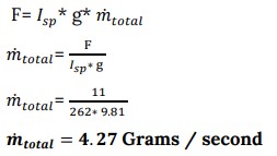
(2) 
The chamber volume is the function of mass flow rate of the propellants and their average density and of the stay time needed for efficient combustion [1].
Combustion chamber volume (Vc): Vc = Ẇtc*V*ts
Characteristic length :It is defined as length that a chamber of the same volume would have if it were a straight tube and had no converging nozzle section.
Characteristic length for the above propellant composition is assumed to be same as Hydrazine because the HAN and Hydrazine belongs to the hydroxylamine salt group.
 [1]
[1]
While designing the combustion chamber, proper value of L* is to be considered because an increase in L* beyond a certain limit results in decrease in overall engine system performance. In case of operating monopropellant low thrust engines the contraction ratio varies in the range from 1.58 to 5. Design of very high contraction area ratios (> 5) have difficult in maintaining stable boundary layer, adjacent to the throat [1].
2.2 Selection of Chamber Internal Profile
The configuration of the combustion chamber is cylindrical which provides sufficient surface area for cooling. For this engine configuration, semi convergent angle of 15 degrees has been selected, favoring a lower heat flux and thereby maximizing the life of the chamber. For current engine configuration the nozzle throat has the contour of circular arc with a radius of R ranging from 0.5 to 1.5 times the radius of the throat. The half angle of the nozzle convergent portion is 15.
Convergent portion length
(3) ![]()
(4) ![]()
Where
The half angle of the convergent portion is assumed to be 15 to 20 degree.
R= radius of curvature at the throat it is assumed to be 0.5 to 1.5 times the
Here assumed as
![]()
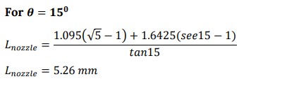


The cross sectional area of the combustion chamber is assumed to be equal to the inlet cross sectional area of the nozzle

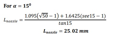
Divergent portion length
(5) ![]()
Where 𝛼 = half angle of the divergent portion
The half angle of the divergent portion is assumed to be 15 to 20 degree.
R= radius of curvature at the throat it is assumed to be 0.5 to 1.5 times the ![]()
Here assumed as
R = 1.5![]() * 1.095 = 1.6425 mm
* 1.095 = 1.6425 mm
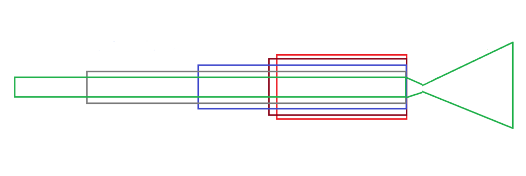
By assuming the diameter of the chamber is not necessarily equal to the diameter of the nozzle inlet [8]. So here in this the diameter of the nozzle inlet kept constant and the design calculations are started by considering the Length of the chamber is equal to 10cm, 5 cm and 2.5 cm for the constant chamber volume. so the variation of the chamber cross sectional area is calibrated for the constant chamber volume.
Fig. 1. Chamber volume and Length variation
Table 3. Chamber volume and Length variation
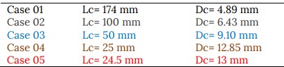
Here in this paper we considered case 05 dimensions of the chamber and CFD simulation is done on this model.
Fig. 2. 2D Chamber model
3. Results
In order to verify the design quality of the nozzle flow field investigation of the nozzle has to be studied. A 2-D axis symmetric computational simulation of the flow field is necessary, which may be either developing a code or by using commercial code. In the present study computation has been made to obtain flow through the nozzle using commercial software FLUENT. In the present study two dimensional structured grids were generated on the nozzle profile. For axis symmetric computation, quadrilateral cells with map scheme was used for grid generation.
The boundary conditions values are taken from NASA-CEA code.
Table 4. Boundary conditions

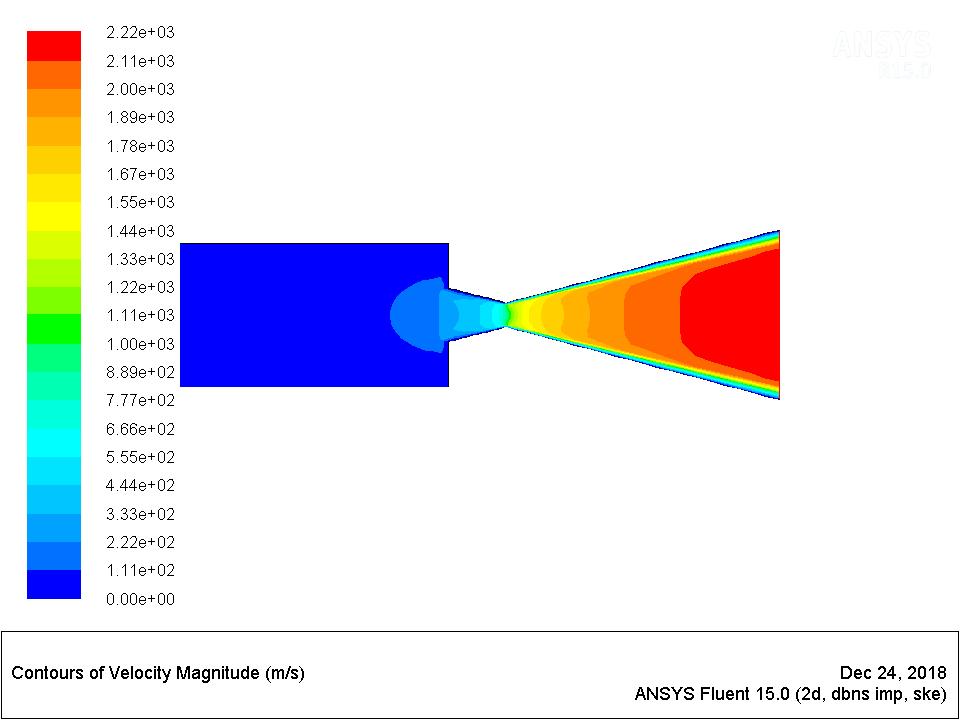
The following results contains the information about the nozzle pressure, velocity, temperature and mach number variation along the nozzle and domain for HAN mono propellant combination. The adiabatic flame temperature of the HAN combustion is around 2294 K. The velocity of the exit gases of HAN combustion is around 2240 m/s. The Results of Nozzle Flow Analysis is tabulated in Table 5.
Fig. 3. Contours of Static Temperature
Fig. 4. Contours of Mach number
Fig. 5. Contours of Velocity magnitude
Fig. 6. Contours of Static Pressure
Table 5. Nozzle Flow Analysis Results

4. Conclusions
In this work we successfully simulated the rocket performance parameters of small spacecraft reaction control thruster for HAN based mono propellants, analytical calculations and flow simulations are done for the standard size11 N thruster. HAN based mono propellants in AOCS thrusters provide high specific impulse which is suitable for use in spacecraft AOCS operations. For the thrust chamber modeled at 11N of thrust and chamber pressure of 16 bar with the propellant combination of HAN+ Methanol+ AN + H2 O shows a very good consistency when compared with computational results. From the analysis result it is found that monopropellant engine with the propellant combination of HAN+ Methanol+ AN + H2O is suitable for design of spacecraft AOCS thrusters.
References
[1] Huang, D. H., Huzel, D. K. (1971, January). Design of Liquid Propellant Rocket Engines Second Edition. Special Publication, Work of the US Gov.
[2] Naresh D. C, Debadatta Mishra, N Karthikeyan, R Narayan (2018, October). Flow analysis of HAN based mono propellant thrusters for space applications. In 32nd National Convention Of Aerospace Engineers (NCAE2018), Bit Mesra, Ranchi.
[3] D. A. Goza (2017, July). Investigation of a hydroxylammonium nitrate thermocatalytic thruster on “green propellant”. 6th Russian-German Conference on Electric Propulsion and Their Application, Procedia Engineering, 185, 91-96.
[4] Hatem Houhou, Hemza Layachi and Abd Elmajid Boudjemai (2020, January). Design of the thrust chamber: dimensional analysis of the combustion chamber and the nozzle of rocket engine using LOX/LCH4 propellants. IOP Conference Series: Materials Science and Engineering.
[5] S. Senthilkumar, Dr.P.Maniiarasan, Christy Oomman Jacob, T.Vinitha (2013, August). Design And Analysis Of Thrust Chamber Of A Cryogenic Rocket Engine. International Journal of Engineering Research & Technology (IJERT), 2(8), 240-248.
[6] George P Sutton and Oscar Biblarz (2001). Rocket Propulsion Elements. John Wiley & Sons, Inc.
[7] Fukuchi B Apollo, Nagase Sakac Maruzumi Haruki , Ayabe Munaco (2010, January). HAN/HN-Based Monopropellant Thrusters. Engineering Review, 43(1), 22-28.
[8] K. Neff and P. King (2009). High Performance Green Propellants for Satellite Applications. 45th AIAA/ASME/SAE/ASEE Joint Propulsion Conference & Exhibit, Moog Inc. Published by the American Institute of Aeronautics and Astronautics.